


PaulMc
-
Posts
949 -
Joined
-
Last visited
-
Days Won
4
Content Type
Profiles
Forums
Events
Gallery
Blogs
Posts posted by PaulMc
-
-
Econoseal J series connectors are what you want, see Polevolt link below. Alas they too only ship to UK currently.
http://www.polevolt....Connectors.html
They are made by Tyco Electronics http://www.te.com/ca...BML=10576,25076
i would imagine TE have distributors in Belgium
Econoseal J Series are a different connector completely, they will not mate with NAS Lamps.
The connectors for NAS Lamps are TE (AMP/Tyco) Econoseal III 070 series.
Most TE distributors will have a 'Minimum Order Quantity' (MOQ), which is usually in 100's (sometimes 1000's).
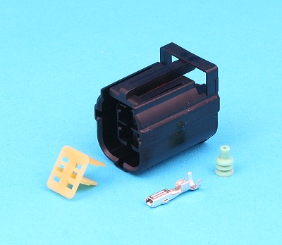
Each female Econoseal III connector consists of 4 components -
Connector HousingFemale TerminalsWire SealsSecondary Terminal Lock (the little Yellow bit on the front)There is a different part number for each component and some of them will have different MOQs to others

There are a few people ship worldwide from ebay
http://www.ebay.co.u...#ht_2280wt_1272
http://www.ebay.co.u...#ht_2224wt_1272
I just searched 12v connector waterproof.
Jason.
The first link is to what looks like Chinese knock-offs of Delphi Metripack connectors.
The second is to TE Superseal connectors (probably Chinese knock-offs as well, from that seller).
Neither of these will fit NAS lamps.
Polevolt is the cheapest for these but, as said above, they don't ship abroad.
Autosparks and VWP both ship abroad -
Auto Sparks -
http://www.autospark...roducts_id=1770

http://www.autospark...roducts_id=1771

They also do them pre-crimped to wire tails with Bullets, for upgrading older Defenders -
http://www.autospark...roducts_id=1392

On VWP's website, they can be found in the 'Lighting' section near the bottom of the page -
http://www.vehicle-w...hting/round.php
They list them with the Durite catalogue numbers - 01252 and 01253
.
-
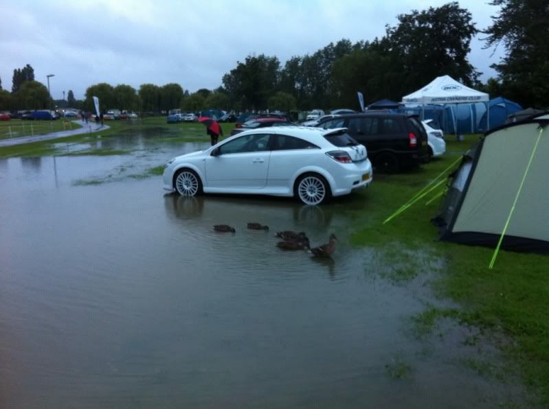
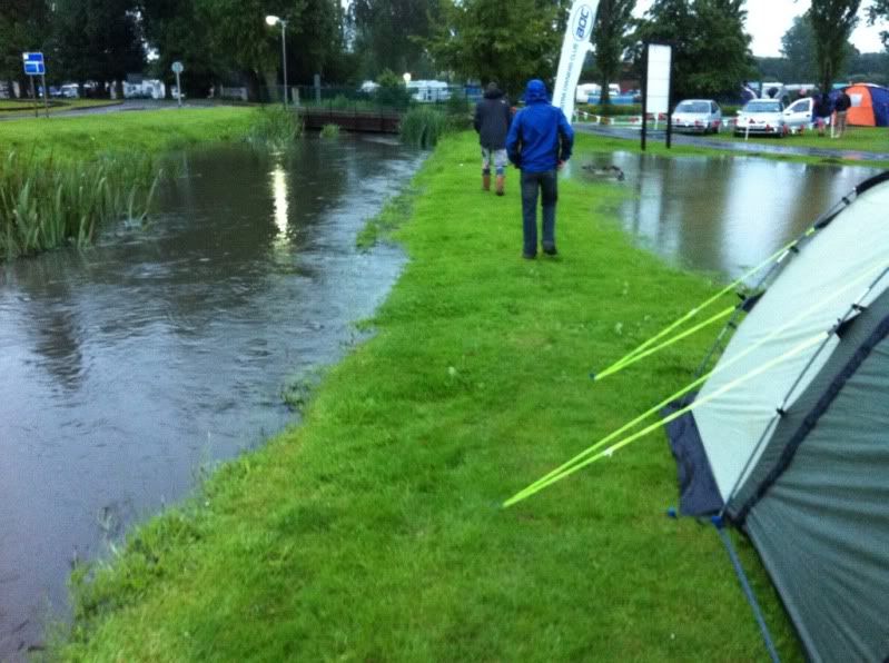
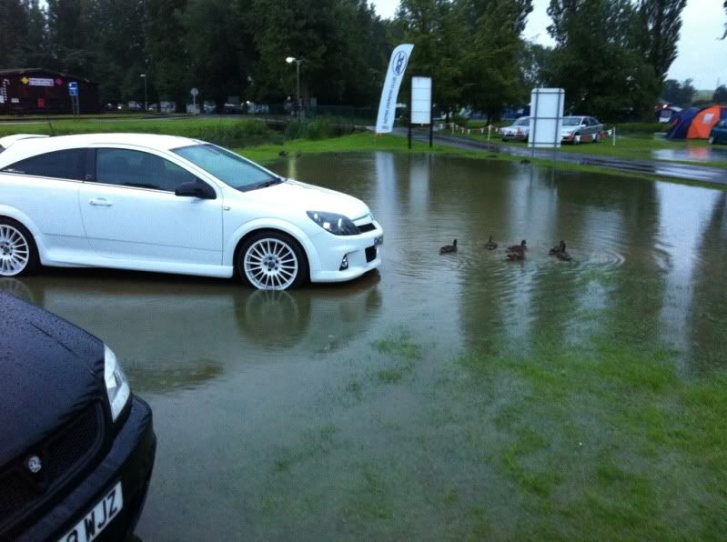
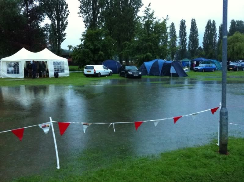
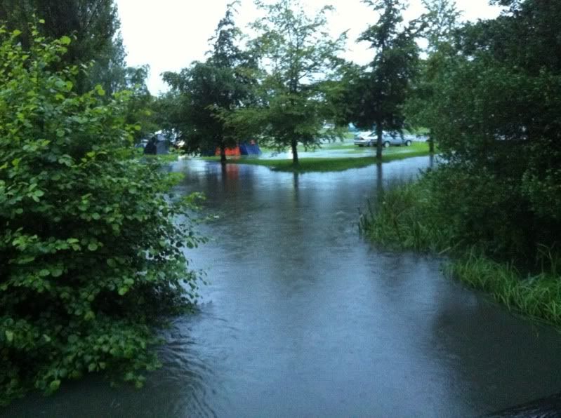
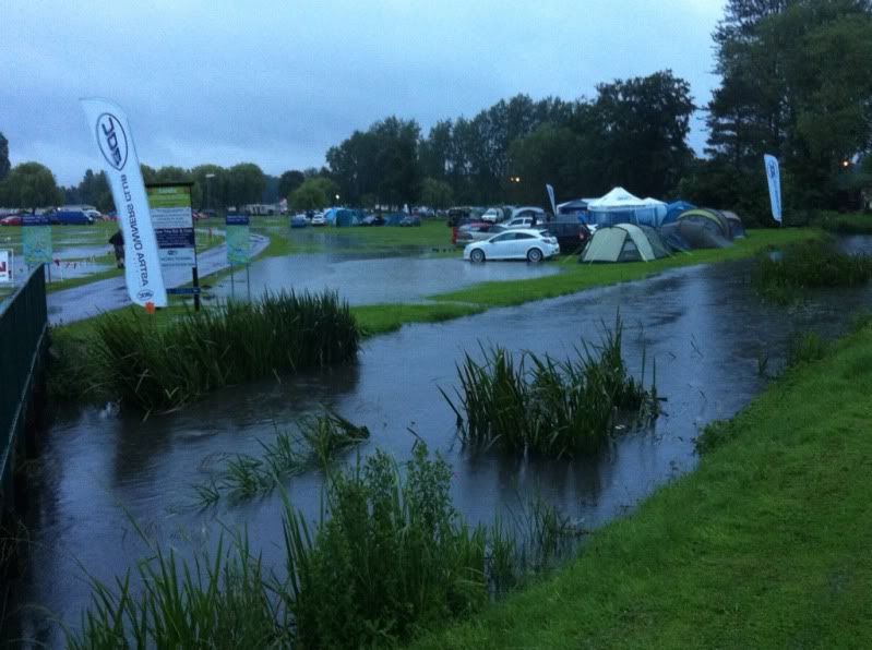
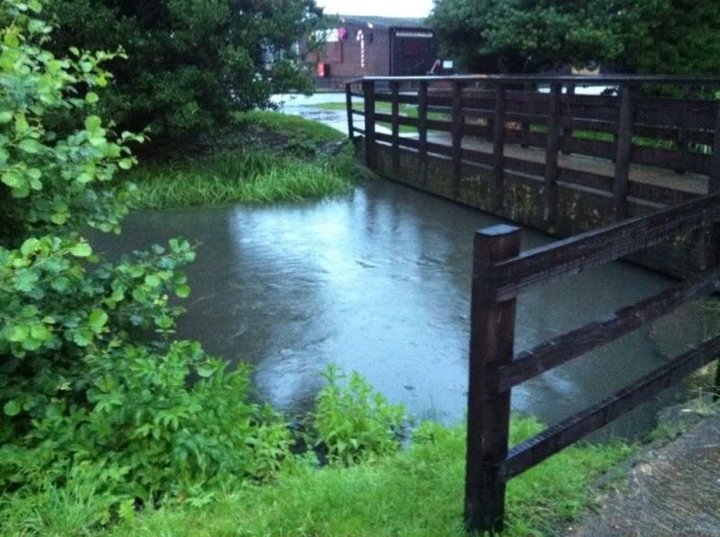
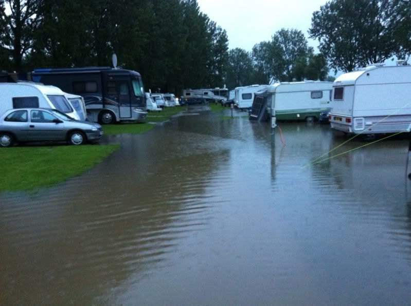
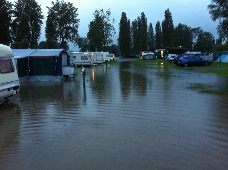
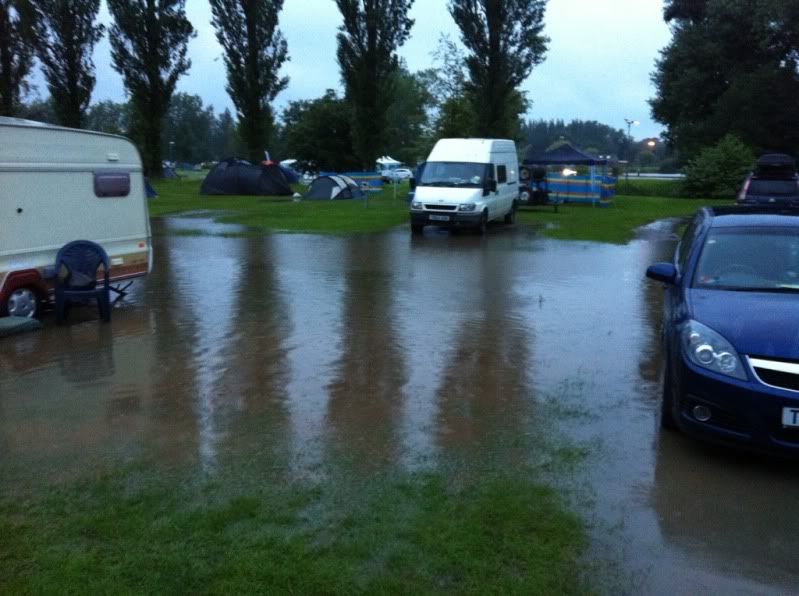
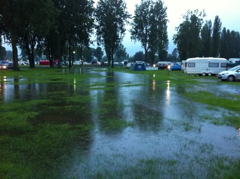
Let's hope it dries up then, as the car show at billing this weekend has been cancelled as it's waterlogged.
This weekend at Billing (13th - 15th July) has been a complete washout for the Vauxhall Bedford Opel Association (VBOA).
The event has been abandoned.
Here are some pics from the Astra Owners Club forum - http://www.astraowne...ad.php?t=363447


.
-
there wasn't a illumination bulb/holder with it but it does have the facility for illumination, I have the bulb/holder from the plain on/off latching switch & the front heated screen lens, now swapped to the new momentary switch.
so on my circuit diagram, I feed the switch from timer terminal 8 & send other side to earth & switch the warning light from timer terminal 5 & other side to earth.?
Timer terminal 8 is connected to terminal 85 on the power relay and one terminal of the switch's warning light (other warning light terminal goes to earth).
Timer terminal 5 goes to terminal 1 (or 5) on the switch, with the other terminal to earth.
So that -
When you press the switch, terminal 5 of the timer relay is earthed momentarily and the timed period starts.
During this timed period, the timer relay's output triggers the power relay and lights the switch's warning light.
.
-
According to my Britax catalogue, 511-007 is a non illuminated, non-latching, single pole on/off switch.
It switches across terminals 1 and 5
I did a Google search for SWF 511-007, and came up with this image from the Hella catalogue (same as from my Britax catalogue) -
(Britax 511-007 is the same as Hella 6GM 004 570-051)

.
-
got my momentary switch oday, it has 2 terminals in positions 1 & 5
looking at terminal face of the switch they are numbered
1 - 2
3 - 4
5 - 6
7 - 8
odd numbers on left as I'm looking at the terminals
off position [posn.] is rocker upper end in & on posn. rocker lower end spring loaded - makes contact & returns to off posn.
switch on indication light is 2 seperate terminals
Did you get a diagram with it?
Do you have a SWF Britax part number?
.
-
never that existed till now,
to late for me as I've got the PRC4427 on it's way to me, I know this will fit & work, as it is the original unit in my '89 110.
I don't think Brit-car know it's a similar item either as they weren't aware that PRC4427 is the same as AMR325, until I asked about it.
If it'll do the same job as PRC4427, it's almost a third of the price

the parts info http://www.numcat.ru...ver/p/31/53684/ item 12 says it's a switch lighting not a VSS. Very strange, wonder why it's used on the tomb radier vehicles.
Microcat doesn't make it too clear, but it looks as though this was fitted in the circuit for the roof lights - perhaps so that they could only be used with the engine running?
.
-
a bit of useful info I've learnt today, the later version of the Voltage Senstive Switch is
AMR3325 -- No longer available
but the earlier version PRC4427 is still available form Brit-car.http://www.brit-car....php?xProd=89705
I happened across this one the other day -
STC61888 SWITCH RELAY LIGHTING TOMB RAIDER DEF
£54.04 (+ £10.81 VAT in EU)
http://www.brit-car....hp?xProd=103436

I wonder how this one differs to PRC4427 and AMR3225
.
-
PaulMc -- when the new switch arrives, I'll post a photo/diagram of it's connections.
also on a elctrically related subject are you able obtain or know where I can get the treminals/plug for the 300tdi/td5 type interior lights IIRC the part number is YPC10028
I started doing a diagram of switch connections, then thought that it might be better to wait and see what switch you had

As for the interior light connector YPC10026, it's another of those Sumitomo HMDC .120" (3mm) connectors, that isn't available commercially from Sumitomo (see - http://forums.lr4x4....showtopic=74109)
If you had a used connector shell, then the terminals are YPL10003, which Land Rover list for around 75p each, but they haven't had stocks of these since early last year (I bought the last 2 pieces held in stock
 )
)I can't find anyone with stocks of Sumitomo HMDC .120" terminals, so no joy there.
A lot of suppliers will refer you to the dimensionally similar Sumitomo MTW .110" (2.8mm) connector/terminal, as an equivalent, but I'm not sure if it will fit the interior light - I will investigate and let you know.
.
-
I've just printed your info above, thanks again

on my diagram above the light wasn't connected to anything except earth.
my diagram above connects the light to Timer terminal 8 via 70 amp relay terminal 85 as that's the switched on power to energise both relays.
switch is a on/off manual latching type, should be able to get a momentary variant tomorrow.
as for terminal 5 on timer not sure how to get that to switch to earth, my 110 is the same model/year as yours so doesn't use the td5 switching to earth way of operating circuits.
It's easy

Ideally, your momentary switch needs to have separate terminals for the warning light's live and earth, i.e. - not connected to the switch's output.
Although, having said that, if the warning light is a bulb (and not an LED), it doesn't really matter if the warning light is internally connected to the switch's output, as you're taking the output to earth, so you just feed the warning light through the terminal that would normally be used as it's earth.
On the switch's switched terminals -
The input terminal goes to terminal 5 on the timer relay
The output terminal is earthed
So that, when you operate the switch, the wire from pin 5 on the timer relay is momentarily switched to earth.
I'm not sure if I've explained any of that clearly

I'll draw-up a couple of diagrams which will, hopefully, explain it a bit clearer.
.
-
Ralph,
I've been looking at this again.
The switch warning light can be taken from terminal 8 of the timer relay (I'm not sure if that's what your diagram already shows
 )
)There's a thread that deals with wiring-up a heated windscreen, using PRC6796, here - http://forums.lr4x4....showtopic=19100
Post #6 has a wiring diagram for PRC6796, used with a 3 terminal windscreen - http://forums.lr4x4....06
Another thing that occurred to me was that your switch needs to be a momentary (non-latching) switch, and you need to momentarily switch terminal 5 of the timer relay to earth, to initiate the 8 minute timed operation.
.
-
further to my last reply in 2006
 this is on my 1989 110, so there are no earth switching wiring like the Td5 vehicles.
as I'm on a weeks holiday, thought it was time to get the front heated screen connected.
I have suitable on/off rocker switch with ON warming light
the timer relay PRC6796 as used in various range rovers
a 70amp relay
30amp fuse & hlder
screen is the 3 terminal variant, I know the centre terminal is Earth & outer terminals are 12v feeds to each side.
will my diagram below work ??? the 1000 dollar question.
what size wire should I get ? there is a auto elect supplier up the road, so wire/terminals shouldn't be any problem.
Ralph,
The diagram looks OK.
The only thing I would say, is that the warning light on the switch needs to be fed from terminal 87 on the 70A relay.
If your switch is the type where the warning light is fed internally from the switch's output terminal, it won't be suitable for this type of circuit.
On the 2002 Defender, with a 2 x terminal screen, Land Rover use 4.0mm2 as the supply and earth.
Having a screen with two heating zones, you can afford to make the supply to each live terminal from lighter gauge cable, as long as they both run all the way back to the source (terminal 87 of the 70A relay).
I would probably go for 2 x 3.0mm2 cables from terminal 87 of the 70A relay, running to each live terminal on the screen.
And the common earth from the middle terminal, in 6.0mm2.
.
-
just fitted those plugs to my 2 amber grille repeater lights, wish I 'd know about the terminal gripping the seal, I have passed the wire through it though.
Some people crimp the wire seal grip with an 'F' crimp to grip the insulation, the same as you would for an unsealed terminal, and slide the wire seal over the crimp.
This isn't how they were designed to be used, but the seal will still work OK.
.
-
The connectors are Tyco (AMP) Econoseal connectors, available from numerous suppliers, Polevolt is the cheapest that I've found -
http://www.polevolt....Connectors.html
When you cut the old lamp unit off, clean-up the individual wires and BEFORE stripping the ends, slide the wire seals over the wires, in the orientation shown -
 .
.  .
. 
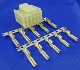
The conductor should be crimped with an 'F' crimp (sometimes called a 'W' crimp) -

The wire seal should be crimped with an 'O' crimp -
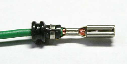
(this picture is of a terminal from a different connector series, but it illustrates the 'O' crimp nicely)
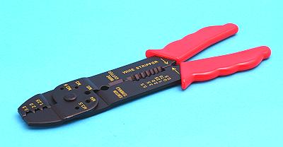
The proper tool to crimp these is expensive, but an acceptable job can be done with a cheapo crimper for un-insulated terminals, like this one from Polevolt -
http://www.polevolt..../info_TT70.html
Once the terminals and wire seals have been crimped and inserted into the connector housing, the secondary terminal lock (yellow plastic bit, in the pictures above) is clipped into place on the front of the connector.
.
-
Ok that answers my question thanks.
I have 18" mondials on my D2. I have been looking at the General Grabber AT2 255/55/18. But will have a look at the BFG's and compare. I'm only looking to do light off roading and it is my daily drive so they will need to be practical.
Cheers
Terra Dog
Where are you looking at these?
I've got General Grabber AT2 255/55/18 on Mondials, on my DII
I'd like to buy some more, but they're no longer stocked/made, because of some EU cr@p about noisy tyres

.
-
C1040-14 is cavity 14 in C1040, it's on the wiring diagram page for the heated windscreen.
It would be ideal for daylight running lights, as it means that they will only be (switchable) on when the engine is running.
.
Sat13 has informed me that he couldn't get the WN wire from C1040-14 to C1624 to trigger a standard automotive relay.
I've asked around, and it would seem that the WN wire only provides a 'signal voltage' to the electronic HFS Timer, it's incapable of providing sufficient current to drive the coil of a relay.
I was told that a better place to pickup an 'engine running' supply under the driver's seat, would be from the main power relay, which is switched by the engine ECU, which detects the engine running/charging, from connections to the alternator.
I've had a look at the PUMA Wiring Diagram and Electrical Library, and this would be the relays output on - C0063-87 (Brown/Orange wire)
Sat13 has confirmed to me that the Brown/Orange wire on C0063-87 is only live when the engine is running and that it's capable of triggering a standard automotive relay.
.
-
Here's a couple of Military 110s -
FFR

GS

.
-
Hi Chaps,
Can anyone help with this one ?
TD5 normal rear loom to rear TD5 tank with ROW sender unit, obviously they dont fit !
Anyone know if you can get a convertor, or a male to connnector and female to tank connector so I can make one up.
And no the pipes are not connnected before someone comments


Dont really want to cut it off as the whole idea is to keep it TD5 compatable when the time comes to retire the 200Tdi
Ta !

The connector moulded on the tank sender/pump is a Tyco Econoseal 4-way male, the mating female connector is available from Polevolt -
http://www.polevolt....info_ESC4F.html
The one on the loom in your hand, is a Tyco 2.5mm pin/socket series, made exclusively for BMW - Tyco won't sell it to you.
You can buy some bits from BMW - connnector housings, terminals and wire seals. Although, I've not seen a cable mounted male 4-way connector. The male half is usually moulded as part of a device.
My suggestion would be to buy a male and female 4-way Econoseal.
Cut the BMW connector off of your vehicle harness, leaving short tails on the BMW connector. Fit a male Econoseal connector to the tails on the BMW connector, to make a short adaptor loom.
Fit the female Econoseal connector to the vehicle harness.
When you want to revert to TD5, you have then have an adaptor to convert the vehicle loom back to TD5 spec.
.
-
It's for switching my daylight running lights that I am installing in the front bumper. I want to be able to control them through a switch/relay set up, independant of my existing lights being on or off. Your Idea sounds ok but I can't quite picture it, what drg is it on. I am using the complete electrical connector manual but cant find a pic of C1040-14. And yes I would be interested in purchasing some terminals and wire pre-crimped from you. If I could fully understand how to go about installing them.
C1040-14 is cavity 14 in C1040, it's on the wiring diagram page for the heated windscreen.
It would be ideal for daylight running lights, as it means that they will only be (switchable) on when the engine is running.
.
-
What accessory are you going to be using this switch for?
You could use the 'engine running' signal from the instrument pack to switch a relay in the under-seat compartment, the relay would be switching a permanent live, taken from the battery feed to the under-seat fusebox, so that the live to your accessory switch would only be live when the engine is running.
I have the terminals to fit into C1040-14 at the instrument pack, and can supply it pre-crimped to a wire of whatever length you require.
.
-
The wire colours are white, purple and orange. I think you could be on the right track with the link harness, as its a 90 so no rear side doors. If this is correct could this plug be tapped into for a live feed.
They're supposed to be -
Orange
Pink
Purple with a Blue Trace
But, I've come across new looms where the colours don't tally with the wiring diagram.
There's no live feed at that plug.
Orange and Pink are the Lock/Unlock wires from the Alarm ECU (it swaps the polarity on these two wires and pulses the door lock motor)
Purple/Blue is the earth signal (from the door courtesy switch) to the Alarm ECU to switch on/off the interior lights.
.
-
Thanks for all the info, the inline fuse carrier for the glow plugs makes sense now what with the heavy wires, but what would the small white plug be used for. The one that looks like a
3-way AMP 070 Multilock.
I don't think that the connector you've pictured between your fingers is C1217
Can you confirm the wire colours that go into it?
As it looks like C2004, which is where the link harness plugs in, for central locking and courtesy light switches on the rear side doors of a Station Wagon.
.
-
I think that C0621 is an inline fuse carrier for the glow plugs -

It's inline between the battery connection at the underseat fusebox - C0621, and the glow plug relay base - C0215
I can't find any other reference to C1875, but it looks like a fuse carrier, the same as C0621.
C1217 looks like a 3-way AMP 070 Multilock.

The page in the connector reference shows terminals 1 and 2 wired back to CTAP (Central Tap???) in 4.0mm2NW cable - this colour is used for the starter relay supply on 2007MY vehicles (and is too big to fit in an AMP Multilock connector
).It shows terminal 3 also wired in 4.0mm2, but in NS, which is used for the fuel pump relay.
I don't think that there's any ignition-switched lives in the underseat battery box.
For the heated windscreen (if fitted), an 'engine running' control wire from C1040-14 on the instrument pack, runs in a WN wire, to the underseat compartment, to switch the heated windscreen timer relay.
You could 'piggy-back' off of this (if fitted), or run the wire to switch your own 'auxiliary power relay.
.
-
this should help with the wiring connections to plug http://www.reedx.net...5/index.htm#HAZ
LR don't list the plugs as seperate items, PaulMc has the info IIRC, he'll either drop on this post or send him a PM. or try a search in Defender forum for switch plugs or td5 connectors
Thank You Ralph

The Hazard Warning Lights Switch Connector, with terminals, can be bought (from me), here -
http://www.ebay.co.uk/itm/160791448904
It's wired, as follows -

.
-
Hi guys. I've got some lights out behind my dash switches, ( the ones on the side of the binnicle, wash wipe etc ) And the stereo controls dont do what they are supposed to do. Volume changes track etc. Do they just pop off ? I dont want to break them as its just had its mot and everything is working at the mo

The switches just pull forward and unplug.
The switch illumination is done with removeable Orange or Green bulbs -
STC1877 - BULB & HOLDER ASSEMBLY, ORANGE

STC1878 - BULB & HOLDER ASSEMBLY, GREEN

.


 )
) this is on my 1989 110, so there are no earth switching wiring like the Td5 vehicles.


300 tdi chassis loom connectors
in Defender Forum (1983 - 2016)
Posted
C0378/C0392 are 6-way Econoseal III connectors -
The White (as well as Red and Blue) versions of the Econoseal III connectors are impossible to source through retail outlets, and most trade distributors don't stock them, but will order them in with an MOQ of 1000 (for the 6-way versions) and an 8-week factory lead time.
The coloured versions have the same coding keyways as the Black Econoseal III connectors, and are interchangeable with one another.
The different colours are used to aid harness connection in production.
As said above, Polevolt are the cheapest source for Econoseal connectors -
http://www.polevolt....Connectors.html
.