


PaulMc
-
Posts
949 -
Joined
-
Last visited
-
Days Won
4
Content Type
Profiles
Forums
Events
Gallery
Blogs
Posts posted by PaulMc
-
-
Hi all
I need a couple of these switches, anyone know where I can find them online?
thanks!
Rimmer Brothers
http://www.rimmerbros.co.uk/Item--i-YUG000540LNF
LR Series
http://www.lrseries.com/shop/product/listing/13578/YUG000540LNF-FRONT-FOG-SWITCH.html

Also, the correct connector for these switches can be bought from here -
http://shop.dingocroft.co.uk/acatalog/Electrical_Miscellany.html#aZZPLUG01

.
-
I was surprised to discover that Britool, Facom and Mac Tools (as well as Black & Decker and DeWALT) are owned by -

http://www.stanleyworks.co.uk/
.
-
Cheers PaulMc, sorry you sacrificed a switch! the light running through it is 55W, so hopefully should'nt wander much above 5 amps, and if it does the inline fuse should pop anyway. The other lights will be relayed, and the switches for them placed in exactly the same place that you have them! (nice tidy job
 )
)It's OK, I didn't sacrifice one of my new switches just to answer your question

I had already taken apart an old one, that I picked up at an Autojumble, to see if I could replace the switch cap with a modifed blank cap (as I've done with Discovery II and post-2002 Defender switches).
I've found out that doing this isn't really feasible with Discovery 1 Switches, as their construction, backlighting and tell-tale illumination are totally different to the later type of switches
Also, the way they're constructed makes it very difficult to dismantle them without breaking them -
 .
. 
Small plastic clips and my ham-fists are not a good combination
.
-
I've got one of the Discovery 1 front fog lamp switches (AMR4138), in pieces, in front of me.
I would say that the contacts are OK for 5 amps, but I wouldn't be happy exceeding that.
I would also say not to dismantle any of the Discovery 1 switches if you ever want to use them again

Relays cost very little and enable you to keep the accessory supply wiring suitably heavy, to minimise voltage drop, without having a weak link.
I'm using relays with all 3 of the Discovery 1 switches, that I'm using for additional lights, in my Discovery II -

.
-
Hi all,
Am fitting a work light to the disco, 55 watt halogen. Wanting to use a spare standard discovery fog light switch to turn it on/off. Any thoughts as to whether I can run the power straight through the switch (55/12 =~ 5 amps) rather than have it switch a relay? I can't find the amp rating for the switches...
Failing that anyone know if theres a way using a multimeter to work out the amp rating of something..? Though I fear its probably a case of putting amps through it until it gets hot and thats your amp rating....!
Ta for any thoughts/previous expereinces/guesses
Ryan
Discovery 1 (200 or 300) or Discovery II ???
Binnacle or Facia Switch ???
Do you have a Part No. for the switch you intend to use ???
.
-
Cheers Paul,
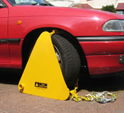
I saw these but I was not sure how good they were, is it a chain and a plate, what stops it comming off the top of the wheel?
Jason.
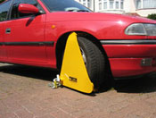
There's a chain welded from the top of the clamp to the bottom right side. This chain has another chain, on a sleeve, that's long enough to wrap around the axle/suspension, which feeds out through a hole on the bottom left and is secured with a BIG padlock.
Here's some fitting instructions I found at http://www.triangle-clamp.co.za/fitting_instructions_1.htm -
1. Rest the triangle plate against the wheel with the chain hole at bottom left and chain loop (the piece of chain with both ends attached to the triangle plate) looped over the right side of the tyre.
2. Pass the unattached chain end around the back of tyre, and over the vehicles suspension arm.
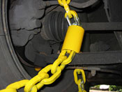
3. Collect the chain end from behind the left side of the wheel and pull to take up all the slack in the chain loop.
Now pass the chain end through the chain hole and pull the chain again until the triangle plate fits flush to the tyre and covers the wheel nuts.
Note: you may need to lift the clamp.
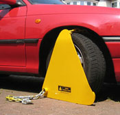
4. Thread padlock shackle through chain link as close as possible to the chain hole to ensure a tight fit of the clamp against the wheel, and lock padlock.
The vehicle is now immobilised.
.
-
Where can I get a set of these?
I'm not sure they're still available

Although, this place are still listing them (scroll down to the bottom of the page) -
http://www.aklocks.co.uk/catalog/vehicle-locking/vehicle-locks
.
-
My mate is a Bailiff, he uses 2 types of Metropolitan Police approved wheel clamps to immobilise vehicles that have been siezed, neither of which will fit Land Rover sized wheels -
The Police Wheel Clamp -

The London Triangle Clamp -

However, there is a version of the London Triangle clamp that will fit -
HGV Wheel Clamp -

I've got one of these HGV Clamps on my 110 -
 .
. 
You can buy them online, here - http://www.london-wheelclamping.co.uk/shop1/wheelclamps.htm
.
-
Safeways D120' locks are really the safest
Are they still available Jim?
If so, where can we buy them?
(from you perhaps
 )
).
-
I read a post on one of the forums (I cant remember which one) and it mentioned using "Hard Hat" paint to refurb Steel wheels. The Thread had pics of a series of Defenders in Matt Black -one of which had modulars repainted in a silver that was very close to the original Modular wheel colour.
http://forums.lr4x4.com/index.php?showtopic=53308
.
-
The Fog lamps and any Driving lamps have very different light patterns.
Generally Fog lamps sit low on the bumper. Driving lamps sit above the bumper / grille.(or on the roof)
I'm fully aware of the difference in beam patterns between fog lamps and driving/spot lamps

My point was that if fog lamps are used to supplement main beam, as long as they extinguish when main beam is dipped, the law regards them as auxiliary lights (i.e. driving lights) and they are completely legal to use in this manner.
As detailed in the thread I linked to above, this can easily be achieved by using an ON/OFF/ON switch to select whether the fog lamps are - triggered by side lights / always off / triggered by main beam
.
-
Interesting to see if the fog lights can be used as driving lights. As wel LR4x4-ers all know, it's illegal to use fogs when the visibility is better than 100 metres (although you wouldn't believe that - loads of prats drive with them on illegally/unnecassarily).
If they could be changed to driving lights (i.e. come on with full beam) you would get much more use out of them...
If fog lights are used with main beam and extinguish when dipped, they are regarded as driving lights (the beam pattern of the lamp is irrelevant) and are legal.
There's a thread about this here - http://forums.lr4x4.com/index.php?showtopic=54312
.
-
Does this mean that both filaments are now on inside the H4 bulb? Interesting to know if this shortens the life at all.
Kev
Yes, both on together.
I did wonder about the bulb overheating or having a reduced lifespan.
Trawling around the web, it seems that doing this is a popular modification on motorbikes, with some BMWs already jumpered to enable or disable the feature.
As I said above, I'll be adding relays and heavier gauge wire in to the headlamp circuits, to reduce any volt drop and to reduce the current going through the column switch.
.
-
OK, so I am not one of those types to drive around with Fog lights on in broad daylight or dazzle folk on clear nights.
However, I do feel the fog lights are under used - living so close to the coast I can probably count on one hand the number of times I have driven in conditions bad enough to need fog lights. But I do drive dark country roads and feel that the more light I can get the better.
I would like to wire up the fogs to come on with the main beam OR work as standard fog lights. So how would I do it?
Am I right in thinking that if I use a 5 pin relay with one feed from the fog light switch to pin 87 and a feed from the main beam to pin 87A that would be enough - or am I missing something?
To answer your original question -
I've pinched LandymanLuke's Diagram and modified it to show how I would do this, using an on/off/on switch -

.
-
Useful info, cheers.
Mine already does that (both on together) "as per other markets" so I wonder if this can also be set using the Nanocom/Test Book?
I had a look through RAVE at the programmable options and that isn't one of them.
Looking at the circuit diagram, it appears to be good-old-fashioned switching, with no involvement of the BCU or IDM (unlike the front fog lights
)Is yours a facelift?, if so, they have separate main and dipped beams, which do stay on together.
Mine is a '99 with H4 headlamps.
.
-
My 1999 Discovery II (with H4 headlamps), like my old Range Rover, switches off the dipped beam when switching to main beam.
You can see the effect of this by 'flashing' - as this flashes the main beam, without extinguishing dipped beam.
But, when you pull the switch all the way back to latch on main beam, the dipped beam extinguishes, throwing most of the light 'down the road' leaving a (relatively) dark area in the foreground.
I had been using my front fog lamps to fill-in this dark area, but this is a pain as they have to be switched on separately and don't extinguish when you dip the main beams.
I've now 'fixed' this annoyance, by releasing the Blue/Red (UR) wire's terminal from cavity 2 on the Lighting Switch Connector (C0041) and moving it to cavity 1 - dipped beam now stays on with main beam (as per some other markets)


I will be making some other improvements to the headlamp wiring in the near future, by installing relays for the left and right dipped and main beams (4 x relays) and increasing the size of the feed and earth wires at the same time.
.
-
Fogs are legal with dipped beam only, what you propose isn't legal I am afraid
That is correct, if they're being used as fog lamps.
If they're used as auxiliary lamps (beam pattern is irrelevant here) they must only be used with main beam and must extinguish when main beam is dipped.
My 2001 Skoda Octavia allows fog lights on with the main beam as standard. I somtimes use them when on very dark country tracks at night when I want to see where the road goes and where the edges of the road has gone to. Really good for getting up narrow and winding tracks and driveways which is what I think the OP is interested in.
Mains and fogs in fog only causes a white out.
My Discovery II's fog lights can also be switched on with main beam (this can be enabled/disabled in the BCU, so it may not be the case for everyone) - I find them a very useful supplement to the main beams.
Down unlit country lanes, the fog lamps fill-in the dark area immediately in front and to the sides of the vehicle, lighting up the verges/hedges/ditches, they also make pot holes much easier to see.
Although, there is an easy (and FREE
) way of improving the spread of light from a Discovery II's headlamps, I'll post that on the Discovery Forum..
-
Me and my mate went to this at Donnington a couple of times and were underwhelmed on both occasions
We only went a 2nd time (in 2006) because a friend of ours, who lives near to Donnington, had just bought a J33p and wanted to go and look for accessories (he was dissapointed)
The best thing we saw there, were the two girls from Roadsure Insurance, who were handing out leaflets inside the entrance to the hall. They were both displaying rather fetching 'cameltoes'

Here's a picture of them that I found on t'interweb from the 2006 show (I've no idea who that bloke is
)
.
-
The kit that M&S has linked to from Raw Components is not a Voltage Sensing Kit.
I've seen that kit before on eBay and had thought then that the description was a load of old 'blah, blah, blah, bull$h1t'
The Relay they show in their picture is a Nagares RL/180-12

Which, AFAIK, is an ordinary Normally-Open Contacts Relay, here's an extract from the Nagares Catalogue -

The description is full of cr@p like -
The kit is on offer to include everything as standard and includes:Brand New Intelligent Voltage Sensing Circuitry- where??? 20 years experience as a qualified auto electrician- included in the kit???
and -
Fully automatic charging of the secondary / auxiliary batteryutilizing integrated circuit technology- where???This only commences once the engine has being started and the alternator has raised the terminal voltage of the vehicle's battery to a pre-determined voltageOnce this threshold is reached then the circuitry comes alive and commences the charging of the secondary / auxiliary batteryand -
It is paticularly suited to the less electrically minded personas only 2 connections need to be made to the vehicle's battery- because they won't be asking awkward questions such as - "where's the VSR".
-
Thanks, VWP was the first place I looked but I am not having any luck finding the connectors on the site to order them and Econoseal in the search box brings up 0 hits. Would you have a name I could search for or a specific URL?
They don't list them with Connectors or identify them as Econoseal, they're on the page with the NAS Lamps -
http://www.vehicle-wiring-products.eu/VWP-onlinestore/lighting/round.php
http://www.roversnorth.com/store/p-5623-tail-lamp-boot-kit-defender-90.aspx contains the boots, they also sell them separately for about 5.50USD.
Obviously a RoversNorth innovation, I've not seen those before.
Definately worth considering for the lamps whose connectors are exposed to the wheelarch, but probably not needed if you're going to seal the connectors in place.
.
-
Does anyone know a source for the NAS signal lamp 2 & 3 pin connectors as well as the rubber boots for them? I found them from Rovers North but $20+ per lamp seems excessive, more than the lamps cost themselves.
I wasn't aware that there was a rubber boot to fit them
Depending on which type of connector you have on your lamps -
AMP Econoseal
 .
. 
Packard Timer
 .
. 
Polevolt sell both types, as do Simtek
Vehicle Wiring Products only sell the Econoseal connectors.
.
-
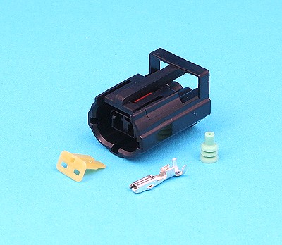
The connector you've pictured is for the 'Shift Interlock' system, only fitted to NAS/Japanese specification vehicles.
.
-
Autopost
Unit 6
The Jubilee Centre
Lombard Road
South Wimbledon
London
SW19 3TZ
Tel: 020 8417 0243
Fax: 020 8540 5437
.
-
Here's Mine, went for Black Silver theme and used a paint called Hard Hat, from the construction industry...
I second that
Rust-Oleum Hard Hat 2176 Satin Black
Gives an excellent finish and dries hard, without being brittle.
.


 )
)


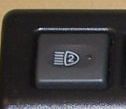
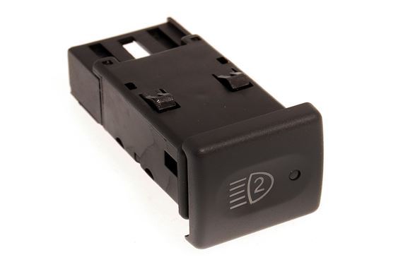
Light switches: where can I buy these online?
in Defender Forum (1983 - 2016)
Posted
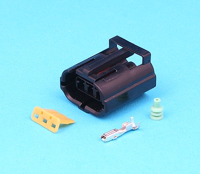
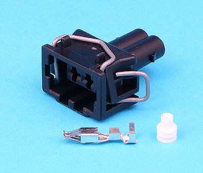
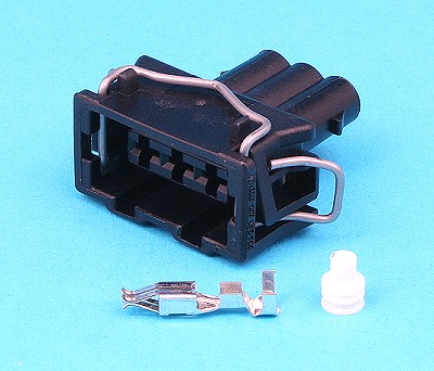
It's the electrical connector (shell and terminals) that plugs into the back of the switch to connect it to the loom.
There are four different coloured connector shells, each with different keyways, to stop inadvertant mis-connection between different switches.
The Defender Front Auxiliary Light Switch, YUG000540LNF, uses the Black connector shell.
If you're using the switches for accessories, are you aware that YUG000540LNF is not a conventional on/off switch?
It's designed to switch an earth path, which means that if you want the Green back illumination and Orange tell-tale LEDs to work, then you have to use it as designed.
It's no great hardship to use it to switch the earth path, it just means that you have to take a wire from the accessory output side of your relay (terminal 87) back to terminal 5 on the switch to light the tell-tale Orange LED.
Here's my diagram of how YUG000540LNF should be wired for auxiliary lamps -
.