


PaulMc
-
Posts
949 -
Joined
-
Last visited
-
Days Won
4
Content Type
Profiles
Forums
Events
Gallery
Blogs
Posts posted by PaulMc
-
-
I have ruined the sedimentor on my ex MOD 110. I tried to get the ( snapped, and wing nut broken ) drain plug out using a drill, and the new one wont fit correctly, so I presume i've ruined the threads. any suggestions?, or do I need a whole new sedimentor?, it's the one on the nearside rear chassis leg if that makes a difference.
Chris.
All the component parts of Sedimenters and Fuel Filters used to be available from CAV/Lucas, I'm not sure if that's still the case now that they're Delphi

Land Rover only supply the complete assembly (NRC9708) or service items, such as Seals, 'O' Rings, Washers and the nasty little plastic Drain Plug that snaps

My tip would be - don't touch that Drain Plug!!!
Instead, undo the long bolt that holds the Sedimenter Bowl to the Head and separate them to clean it out.
Replace the Rubber Seals and 'O' Rings when re-assembling it - they're the same as the ones supplied with Fuel Filters (CAV296 type, or equivalent).
.
-
I believe it's 2005 vintage. The stuff Si sent me (thanks Si!) seems to tally up with what I've seen with the dashboard apart.
There's no easy place to pickup the Blue/White Main Beam wire behind the dash of a post 2002 Defender.
Your options are -
The Column Flasher/Dip Switch Connector (Pin 5 on Connector C1042)The Main Beam Warning Light in the Instrument Pod (Pin 1 in the 20-Way Connector C0233)The Connector on the back of the Passenger Compartment Fuse Box (Pin 13 on Connector C0581)Any of them could have the appropriate terminal released from the connector housing and cut off of the cable, and then a new terminal of the correct type crimped on to the existing wire with a new Blue/White wire crimped in with it - depends if you can get the terminals to suit.
The easiest option out of the above would be the wire to the Instrument Pod Main Beam Warning Light, it's 0.5mm2 and the Tyco/AMP 040 Multilock terminals (as used in the infamous 'wibbly wobbly speedo' thread) are readily available.
I would suggest releasing the terminal from position 1 in C0233, cutting the terminal off and crimping the cable end, together with a new length of 0.5mm2 Blue/White cable, into the female terminal of something like one of these -
6.3mm Multiple connector kit 1 way
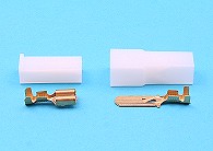
1 way Mate-N-Lock kit. Male, female and terminals
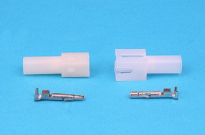
The corresponding male terminal is used for your pickup and the other end of your new length of 0.5mm2 Blue/White cable should have a new Tyco/AMP 040 Multilock terminal crimped on to it and pushed back into position 1 of C0233
.
-
Wiring some lights & bits to a mate's TD5 110, I need to find a source for a main beam feed (live when main beam is on) but preferably without chopping into the high-current main beam wire. I note there are lots of unused connectors in the loom with various colour codes, so I was hoping there might be one somewhere I can use.
Unfortunately the main beam wires behind the dash and fusebox don't have much slack so I'm reluctant to chop them about unless I have to.
Also info on general colour codes / wiring diagrams for something of this era gratefully received

What year is your mate's TD5 110 ???
The wiring on pre and post 2002 models is significantly different, and that's not just the centre console and switches on the post 2002 vehicles.
.
-
Sorry assumed that the LR spotlight kit came with a relay hence the switch wire, with the otherse if you haven't you need a relay.
You're correct - the LR 'Genuine Parts' Spotlight Wiring Kit does come with a Relay.
.
-
The ARB bumpers are a face mount bumper, so going by that should be fine.
The 8274 doesn't fit an ARB Bumper without modification.
The top of the ARB Bumper's winch mounting face has a folded return on it's top, which prevents the tall 8274 from bolting up against the mounting face and the winch mounting bolt holes are not drilled for the 8274's bolt pattern.
I haven't done it myself (I fitted a Warn M10000 into my ARB and it's a straight forward bolt-up job) but I did look at an 8274 at the time and decided against it, mainly because I got a good deal on an M10000

There's an article on The D-90 Source which gives details on the modifications required to the ARB Bumper to fit an 8274-50, here - http://www.d-90.com/tech/8274.html

... but a 8274 "hangs" and i don't know if the bumper can take it
All winches fitted into the ARB Bumper 'hang' on the four (M12) winch mounting bolts on the face of the bumper.
.
-
Just the Electrical Troubleshooting Manual, on it's own, can be downloaded from here -
.
-
Nice Car (I still miss my old RR Classic
 ) and nice parking garage too
 Anyway, go to the downloads page on http://green-oval.com/joomla/index.php and download RAVE CD 3
That contains the Electrical Troubleshooting Manual (plus every other manual/handbook) for the 1995 RR Classic.
The wiring diagrams are a bit dis-jointed, but it's all in there.
.
-
Assuming you're the UK and have a RHD vehicle -
The Switches for both Front and Rear Fog Lights, Heated Rear Window and Central Locking all go back to Earth Header C0760, behind the Instrument Binnacle -

Earth Header C0760 gets it's earth through Earth Header C0018 in the Driver's Footwell, as does the Front RH Fog Lamp, the Driver's Door Lock Motor Switch and all the Central Locking Relays in the Passenger Compartment Fusebox -

I recommend that you start at Earth Header C0018 and make sure that there's no corrosion on or around it's mounting bolt and then check that each wire's terminal at the Header is clean and bright, as well as the 'commoning' Header Cap.
The Header is quite easy to dismantle -
Unbolt the whole assembly from the A Pillar, lift the locking tabs at the side of the Header Cap and pull the cap off of the Terminal Housing.
The Terminals can be removed from the housing by lifting the locking tab above each Terminal (from the front of the housing) with a small screw driver, as you gently pull on the cable - and it should pull out of the housing.
Ensure everything is clean and bright (and not green and tarnished), then re-assemble it all with a smear of Vaseline on the Terminals, the Header Cap Terminal Tabs, it's Mounting Tab and Fixing Bolt - to keep it that way.
.
-
I plan to replace the solenoids as the original ones are past their best and hence am looking at an Albright.
I notice that it is possible to get copies of the original Albright solenoid for about half the price.
Now, I know that these will not be as good but how do they rate ? As good as original / avoid / OK for non-comp use ?
Have a look at this -
http://forums.lr4x4.com/index.php?showtopic=9118&view=findpost&p=96324
.
-
Folks,
I have finally decided try and change the wiring on my 1993 200 tdi to change from the "old" style turn knob rear wiper switch to the 2002 style push button with seperate wash switch.
Does anyone have a wiring diagram or instructions on how to change it over, I know the swich cannot take the load and will require a relay.
Some one must have done it... I looked at the sites will reedx.com, but I cant find any specific reference to swapping rear wiper switches.
Cheers
You will require a Change-Over (5-pin) Relay, wired as below -

The complete Wiring Diagram for the 2002 Defender can be downloaded from here -
http://exerro.com/oldsites/2009/indigoprime.com/landrover/
.
-
Coming at this from a slightly different angle, I'd use the oil pressure warning switch as a way of switching the earth side of the unit, possibly through a relay but I doubt it'll require much power. That way the timer is only running when the engine is actually running. You can also use the alternator warning light in a similar way but that's slightly more complicated.
Yes, that's a very good point
.
-
I would like to get the spade connector out of the (brown) connector block so I can reterminate it with the extra wire I need. Can't get it out of the block tho - any ideas? The spades obviously push in but then latch and I can't reverse the process.
There's a white plastic Terminal Lock in those Connectors (Sumitomo HD Series) that has to be released at the back (cable entry side), before you are able to lift the locking tab (accessed from the front) to release each terminal, one at a time. I can give more details if you want.
The correct Sumitomo .250" and .305" terminals to fit these connectors are available from Eastern Beaver -
 .
. 
The .250" terminals are also available from Polevolt, here in the UK, or the KET equivalent, from me, on eBay soon
.
-
Simple really.. .I should have thought that if I wanted a feed that is live only when in position 2 then I should look at the ignition switch. Followed the green stripy wire from the ignition switch back to teh fuse box under the steering wheel and there was a nice connector ready for me to tap in to. I would like to get the spade connector out of the (brown) connector block so I can reterminate it with the extra wire I need. Can't get it out of the block tho - any ideas? The spades obviously push in but then latch and I can't reverse the process.
Also if I can't do that, then I'd like to splice into that green stripy wire somehow. I know Scotchloks are widely used but I feel they must weaken the wire you are tapping in to. Any better ways of doing this. I'm handy with heat shrink and solder but wondered what the preferred method is of tapping into a wire.
Cheers
Dave
DON'T USE SCOTCHLOKS - THEY'RE THE WORK OF THE DEVIL

The easiest way to pickup your feed is to do as cipx2 has said, and take it from an existing accessory that has an ignition controlled live.
My suggestion would be from the Light Green/White trace (LGW) wire that feeds the Cigar Lighter Socket, it's reasonably easy to get at and is protected by a 20A fuse (fuse 15) in the Passenger Compartment Fusebox.
There are several other places you could pickup an ignition controlled live from - on one or more of the Passenger Compartment Fusebox Connectors (fused side), or from one of the under-dash Power Distribution Headers that are fed from them.
There's not a lot of slack cable in the loom and access can be tight, so the way that I 'tap-off' from an existing circuit is to release the appropriate terminal from the Connector/Header and cut it off. I then bare the end of the existing wire, twist it together with my new wire and crimp them both into a new terminal and push it back into the Connector/Header.
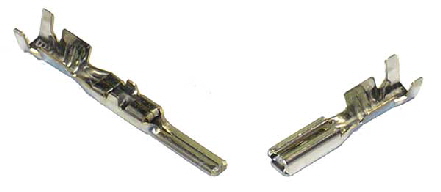
Most of these Connectors/Headers are made by Sumitomo and use the .090" terminal F(8240-4422) (for cables 0.5 - 1.25 mm2) -

New terminals can be sourced from a company called Eastern Beaver

They sell them in sets of 10 x male with 10 x female
Ref: FM090, for $2.90 + P&P (from Japan), here -
http://www.easternbeaver.com/Main/Elec__Products/Connectors/090_Connectors/090_connectors.html
Or the KET (Korea Electric Terminal) equivalent (ST730366-3) from me (much cheaper than Eastern Beaver) - on eBay soon
.
-
Available on eBay from Massey 4x4 at £185 for a pair -
LANDROVER DISCOVERY 2 ROOF BARS - TUBULAR G4 VERSION!!

The listing says that they have 119 available.
.
-
Using the Alternator Charge Warning Light to trigger a Heavy Current Relay works on older vehicles - it's how I initially wired the Split Charge circuit on my 110 and it worked for several years that way, without problems.
But, Mike and the others are right, a VSR is a much better way of triggering a Heavy Current Relay.
The all-in-one VSR/Heavy Current Relays linked to on here are good and will do the job, but are expensive. The Devon 4x4 one is just a Heavy Current Relay and would need a VSR to trigger it.
Land Rover fitted a VSR for various functions on RR Classic, Discovery 1, Discovery II, Freelander 1, Defender, and 90/110 - to switch a relay for the Heated Rear Window, 12S Towing Connector (for Split Charge) and on-vehicle 2nd Battery Split Charge -
PRC4427 (replaced by AMR3325)
 .
. 
 .
. 
Silly money new, but quite cheap 2nd hand.
Combined with a decent Heavy Current Relay, a cheap and reliable Split Charge system can be created, like this -
A quick and dirty twin battery system
.
-
The promotional video for the Armoured Discovery 3 is on YouTube -
The Director seems to cut the end of the "15kg of TNT at 3 metres" scene rather quickly

.
-
Urban Panzer has documented a 2nd battery installation, using the ARB mount, on his website -
http://www.discovery2.co.uk/twinbattery.html
There's a lot of other, very useful, Discovery II stuff on there as well
.
-
Is that a bit the same as cash only, no paypal.
Then at the top, payments accepted ------paypal------
You don't have the option to remove PayPal as an accepted method of payment
Of course, eBay insist on this "for your safety and protection"
- nothing to do with the fact that they own PayPal and cream off even more commission when something is bought with PayPal .
-
I have installed a heated screen with the timer/relay etc and have now got to wiring the switch. It is a 2004 model and I have got the proper switch so that it fits the dash.
Can anybody tell me what the 5 pins (numbered 1-5) should be connected to. I assume that 2 conections are to iluminate the switch and the other 3 for the screen operation but which one is which.
The switch makes a momentary earth path from Pin 1 to Pin 4 for the Heated Front Screen Timer.
Pin 1 is connected to the HFS Timer (see diagram).
Pin 2 is connected to the Dash Illumination.
Pin 3 is not used.
Pin 4 is connected to earth.
Pin 5 is connected to the Heated Front Screen/Relay to light the Orange 'Tell-Tale' LED when the Screen is powered.
Here are the wiring diagram and switch connector details from the RAVE for 2002MY Defender -
 .
. 
The complete Defender 2002MY Wiring Diagram can be downloaded, along with a lot of other useful stuff, from here -
http://exerro.com/oldsites/2009/indigoprime.com/landrover/
For info on the switch connector and terminals, have a look at my posts on this thread -
http://forums.lr4x4.com/index.php?showtopic=26669
.
-
Although it's for a 90, rather than a 110, I thought that you might still find this interesting, as it shows the later type of combined mounting bracket/cover that's used with NRC9708, along with Part No's -
Installing fuel sedimentor on Defender 90
He's also written a few other installation articles, here -
http://www.rebaseonu.net/go/story
Which cover the fitting of the following to his Defender 90 -
Aux drive belt: Dayco vs Land Rover branded Dayco
Are they really the same?
Installing fuel sedimentor on Defender 90
Easy to install using factory parts.
Quick review of Goodridge braided brake hoses. Good performance but connectors differ from genuine, giving room for improvement.
Safari Snorkel installation fiasco
Problems encountered when installing Safari Snorkel model SS-550HF on a LHD vehicle.
Mantec swing-away spare wheel carrier installation
Overview of the installation process.
Some pictures about a problem I encountered when installing Polybush Comfort (blue) bushes.
Allmakes GAL048 steering guard installation
Some pictures of Allmakes GAL048 steering guard mounting on Defender 90.
.
-
It looks like a Slide-Hammer.
I've no idea what for, though
.
-
On Military 110s and civvy vehicles fitted with the optional Sedimenter, it's mounted on the outside of the chassis rail on the L/H side.
In this position, it catches any water or $h1te in the fuel before it gets too far from the tank.
This is also an ideal place to fit something like the CAV D-Wax fuel heater.
The factory fit plastic fuel pipes front to rear, I think that these are less susceptible to waxing in low temperatures than metal pipes.
Have a look at the Military Parts Books in my signature and the Sedimenter pages in Microcat, they show mountings, pipes, etc...
.
-
Yes Paul that's the one I use.
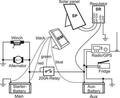
Why the solar panel ?
I have a 30 watt one. It's useless. Wel it give the battery another two hours to run the fridge in Africa. Not here though.
Is that system "bush repairable" ?
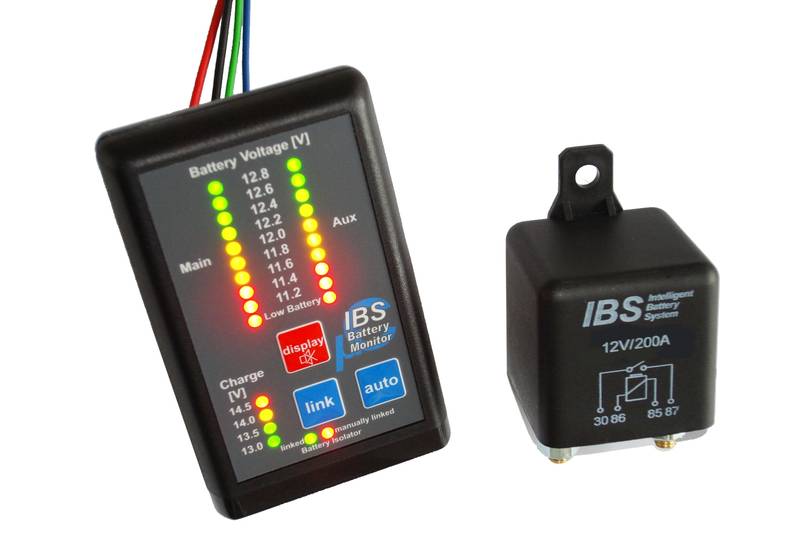
I'm not using a solar panel (no point in this country
) that's just IBS's diagram showing where to connect various devices.The IBS system is 'field repairable' as, ultimately, it's only a relay - albeit with an electronic control/monitoring front end.
.
-
Somebody has removed the Lucas split charge relay box from my desk. Not only that but I can't fing my Lucas book with all the diagrams in.
IIRC the Lucas split charge relay is well marked with where the terminals go to. It's only rated at 70AMPs though.
One small point. DON'T take the wire to the warning light wire on a modern alternator. It will blow the alternator. Take it from an ignition liuve lead. Don't dare ask how I know.....
Mike,
The Relay you're thinking of is the Lucas 33RA (SRB630) Split Charge Relay.

Available from AES - http://www.autoelectricsupplies.co.uk/product/824
 .
.  W1 - Alternator Warning Light** SEE MIKE'S NOTE ABOVE **W2 - EarthC1 - Main BatteryC2 - Auxiliary BatteryC3 - Refrigerator
I've been using one of these Lucas 33RA Relays, without problem, for about 15 years on my 110.
Although, when I finish my Dual Battery and Winch rewire, I'll be replacing it with this -
http://ibs-tech.ch/en/products/dual-battery-system/ibs-dbs-with-uproc.html
which is wired a little differently to the normal Split Charge circuits -
and I'll be replacing the Relay in the IBS Kit with a Tyco/AMP IP67 Sealed 300A Battery Disconnect High Current Relay -

Tyco HCR - ENG_DS_V23132-X0000-A001.pdf
Available on eBay - 300A AMP AMPS 12 V 24 VOLT CAR SPLIT CHARGE POWER RELAY
.


auxillary heaters
in International Forum
Posted
Have a look at this eBay Shop - Aluminium Metalworking Supplies - Car Heater Units
They make a very neat Lightweight Heater Unit for £99 -
They also supply all the installation bits - mountings, ducting, hoses, outlets, etc...
.