


Adam001
-
Posts
864 -
Joined
-
Last visited
-
Days Won
2
Content Type
Profiles
Forums
Events
Gallery
Blogs
Posts posted by Adam001
-
-
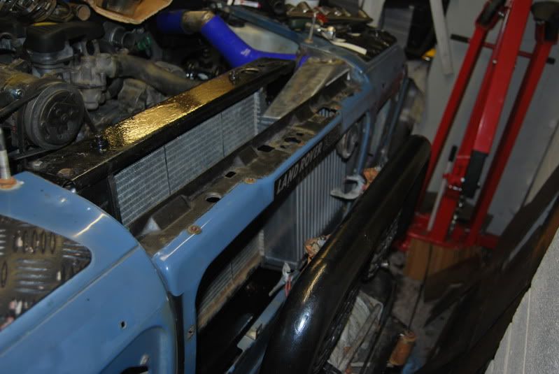
I too went for a DIY approach for a larger intercooler using the 300tdi turbo on a 200tdi.
I decided I wanted the radiator (discovery) to remain as clear as possible as I plan on taking mine to hot climates.
The standard intercooler has approximately 3000cm3 of cooling area. I chose a uprated Mazda RX-7 intercooler with 7700cm3. Well over 100% increase in cooling area.
Fitting was reasonably straightforward, just needed a bit of thinking for a smart fit (chassis modifications, cut off both lower mounts and re-welded the standard discovery surround
Adam
-
Do you have any other symptons? Difficult to start? smoke colour?
I/we had that engine for over 16 years so know it fairly well, like others on here I got 85 from it ok. I did swap to the 200tdi as it is a much better engine, but the 19J is not actually as bad as some people make out.
Piston rings are a common failure on them which cause a significant loss of power. A compression test will show that up.
-
Just to add, Boost is dictated by exhaust gas velocity, if you cut the fuelling, you cut the exhaust gas speed and the boost would drop away anyway. For steady state you won't see a change, the load point will just move.
In short, doing the mod will not improve your economy through theory, in practice it will however purely because you cannot use 70 odd % of the engines power.
This.You'll find if you install a boost guage that when your cruising on the motorway your not generating much in the way of boost anyway, so doing what you suggest would basically do nothing.
The cylinder deactivation works on petrol engines, because running 4 cylinders with a very small throttle angle creates lots of inefficiency, by shutting two cylinders down and running on the remaining two, you end up with a larger throttle opening, and the engine runs more efficiently and thus uses less fuel.
Just one addition on the deactivation, you got the theory but the major increase in economy comes from the reduction in pumping losses from isolating the cylinders (turning the valves off completely), throttle opening is part of pumping losses, but not as great as the effect of pumping the air through the cylinder.
-
Whose that? do you have a link?
Cheers,
Adam
-
Hi,
Currently looking for a set of body sliders, my rear tub below the cappings is a bit messy so want to cover it up.
Does anyone know if anyone sells body sliders for a 110 (6 pieces) or anything suitable? Would like something tubular rather than box like the firstfour ones.
I also have split doors....If not, I'll crack the welder out!
Cheers,
Adam
-
My first advice would be to do some homework on basic electric principles. Not sure exactly why you need something to tell if they are shorting.
Alternators can share the same earth, they earth through the body of the alternator onto the engine mounting bracket. You only need to worry about the +ve side
Perhaps explain a little more and I'll try and help
-
Based on the above posts I'm guessing that I'm correct in my initial understanding that all that would be necessary to fully convert from forced induction to NA would be to: replace manifolds and exhaust with a properly engineered replacement and set the timing and fuelling (accurately) to suit (I'd be going as far to do this on a bench dyno).
Many thanks indeed for your input.
Bear in mind that a bench dyno is purely for use for initial calibration on heavily modified engine / new builds. What works on the bench dyno will not be optimised in a car. You need to do it twice, on the bench then on a rolling road....then to be completely accurate. adjust it on the road. All 3 scenarios having very different flow characteristics
-
Some of these comments just seem plain bizarre! Terrifying in the wet...Very noisy... clearly I have some kind of miracle batch of rubber on mine

If you want silent tyres and amazing wet performance...buy some road tyres
-
Bear in mind the puma dash electronics will pretty much need ripping out and the dash won't work with older models. CANBUS is electrical trickery

-
Yeah that is pretty much what I started doing on my seatbox...then i found 2 broken cables on the seat, started looking for spares and failed miserably...so went back to peugeot 306 seats...lovely and comfy, will upgrade them to the alacantara style when I get a chance.
If your changing your bulkhead keep your aye out for a galvanised one, fit and forget then!
-
Tried it and failed....
http://forums.lr4x4.com/index.php?showtopic=76920&hl=
If you raise the seat up to fit the quad motor assembly in, the seat will be too high. Only way you'll have success is to hack up the seat box, or cut and re-weld the motor set to make it lower profile.
Either way...your better off getting different seats. Also try and find spares for these seats! If something breaks you'll need to buy a spare seat for spares.
-
Confirmed... the 19J is 1/2BSP at both ends. Going to order up some AN10 fittings and convert it all
-
Cheers Phil, I'll order a cheap 1/2" BSP and 20mm adapter off ebay and use those to check
-
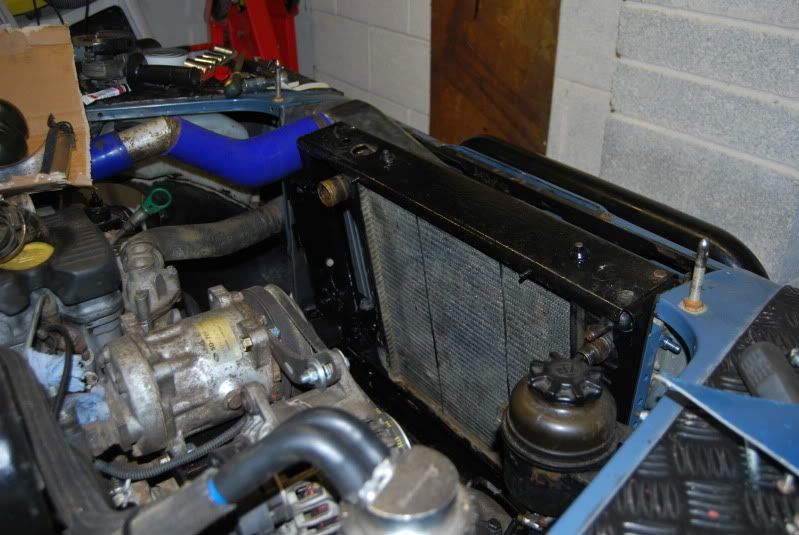
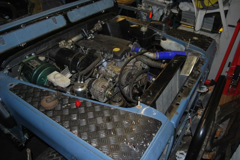
Hi,
Nearly finished with my restoration but the oil cooler pipes are bothering me. I have a 200tdi Discovery Engine with the 19J 2.5TD cooler pipes and the Disco radiator. They worked ok in the standard converted positions but now I have tilted the radiator they are no longer that tidy so thinking of swapping to braided hoses and fabbing some up to suit.
So question is does anyone have any idea what the threads are on the 200tdi, engine side and radiator side. ideally knowing what threads are on the 19J lines would be the easiest as I know there are 2 types of adapter for the radiator side depending on age etc.
Any thoughts?
Cheers,
Adam
-
Getting the nut off is easy...getting the arm off is another story...
-
About to buy mine, will ring around different companies...but in the meantime I'm installing the wiring. At the moment I have run 2 feeds to each bottom corner of the windscreen and a earth to the centre...is this correct?
-
haha the springs really are not evil in these. Pretty basic switches construction wise, case of simple is better I guess
-
I haven't got the switches with me now so I can't check but if I remember correctly the actuator will sit on the body in either direction, so yes you can but you will need to unclip the LEDs and swap them around, so they illuminate the correct parts, should be easy to do....either that or use a SPDT switch as opposed to a SPST switch and just only use one of the outputs, but would still rock twice.
-
I paid £385 on auction off ebay for a non-repaired TD5 Galvanised Bulkhead. Worth the money rather than messing around trying to repair mine!
-
Mine will be tidy whether I use the blocks or not...blocks are nicer I will admit though!
Pretty sure the blocks will work with the mod too
PROBLEM WITH THIS MOD!!....Don't use superglue, it must let of off some kind of vapour, never had this problem before, must be the material the switch is made of. 4 of my modified switches are fine, 1 has a small build up at the base of the resistor causing it to insulate the connection. Will crack out the acetone tomorrow and rectify it. Just a note that to play it safe you are best to use a sealant or nothing as opposed to a glue.
I should note that the switch affected has a plastic roller, not a metal roller like the others so I think it's part of a revised design and the glue must have reacted with the plastic. It's not bad and a simple fix as I haven't fitted it, but it would be a right pain otherwise!
-
 1
1
-
-
Yeah got all mine from MUD UK...I have loads of them...you've seen my wiring diagram haha!
Not using the connectors as I already spent a fortune on the switches...I'm being tight lol
-
Easily done.
All you need to do is find the tracer white/red wire that goes from your ignition barrel to your starter relay. Tap into that wire and put a feed to one side of the starter button, on the other side put any ignition live (white live from ignition barrel)
That means when you press the button it sends ignition live to the coil of the starter relay, therefore turning the starter.
The mods are all low current, 1mm^2 wire is fine.
-
That's a great modification! I'll be doing some of that!
Si
 Thought it might be helpfulGood write up!
Would it be possible to connect the additional wire to the base of the spade inside the housing, underneath the contact strips? I know it would take a lot of fiddling, but it would keep all of the mods inside.
Luke
It is likely possible, you could just run the wire down the other side, would be more fiddly and intricate and you would need to put some more care around how you route it to avoid the internal contacts for pin 1 and 3 and the rocker itself. Would need to take one apart and have a real dig. I'm quite happy with how this mod has worked so wouldn't go through the effort of trying to keep it all internal.
-
Carling Switch Modification
`
Summary
This guide is to show how you can modify a SPDT Carling Contura II Switch to operate in reverse so you have 2 inputs and 1 output but still retain both the indicator LED and the Backlight LED while having the switch do what you want.....But as always, don't blame me if you use my info and destroy your lovely £10 switch
Problem
The Carling SPDT switch assumes it will be used to control 2 loads, whereas in my case I wanted 2 different feeds to control 1 load. The example used here is my roof mounted reverse lights. I want to have the functionality for the relay to either be switched on from a permanent 12V feed or automatically when the reverse gear is engaged. For this to work you have to use the SPST switch backwards from its design intent.
The Carling switches indication LED is wired to one of the output pins, so if you use that pin as a input the LED bar will in effect always be lit regardless of the switch position.
To help explain, here is a wiring diagram of how the internals of the carling switch are set out
- Pin 1 is Output 1 (or 2)
- Pin 2 is Input
- Pin 3 is Output 2 (or 1, however you want to look at it)
- Pin 7 is the earth for both internal LEDs
- Pin 8 is the sidelight feed for the illumination window
Its a little backwards as when circuit 2 is armed the LED bar wouldnt light up anyway. What we need to do is re-configure the internal circuits so the wiring diagram does this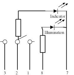
Now we have- Pin 1 is input 1
- Pin 2 is output
- Pin 3 is input 2
- Pin 7 is earth
- Pin 8 is sidelight feed
The modification really is quite simple, to do it youll need the following tools- Small electrical Screwdrivers
- Drill and 1-2mm drill bit (small as possible)
- Tweezers
- Superglue
- Soldering Iron
- Needle nose pliers
- some small solid wire (resistor leg)
First up then take one SPDT switch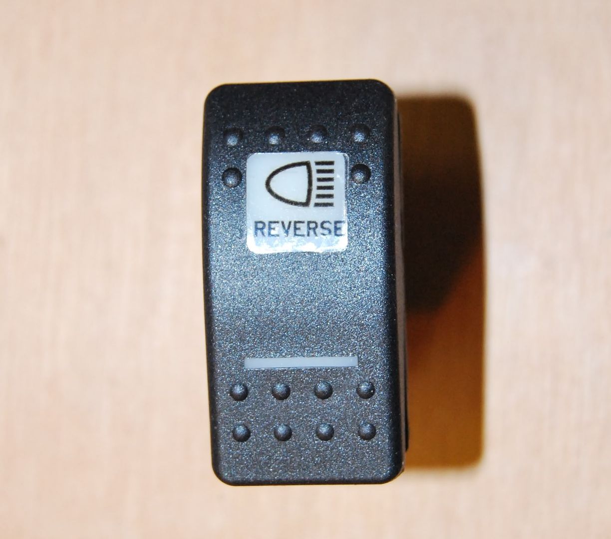
Take a small electrical screwdriver and lever it underneath the 2 retaining tabs on both sides of the switch. As you do it keep some pressure on the 2 halves to prevent it springing apart.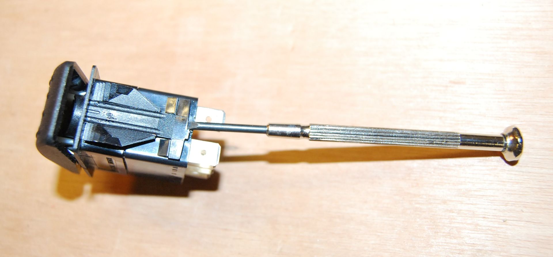
With both retaining clips undone carefully relax the 2 halves to take the pressure off the springs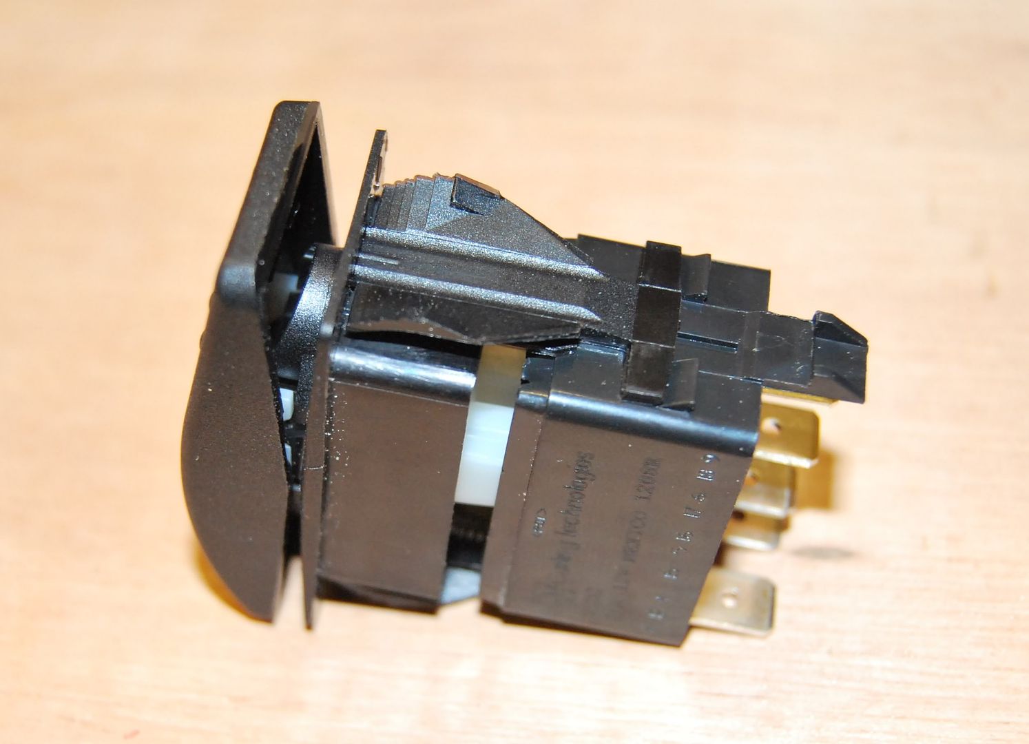
Now with the switch upright and at a 45 degree angle pull the 2 halves apart, this will keep the springs in the base and the roller rocker in place in the top half.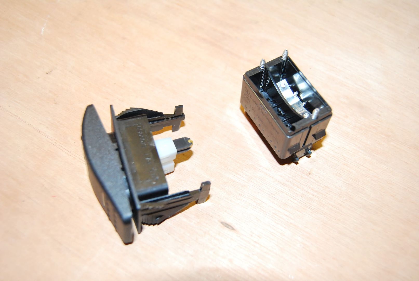
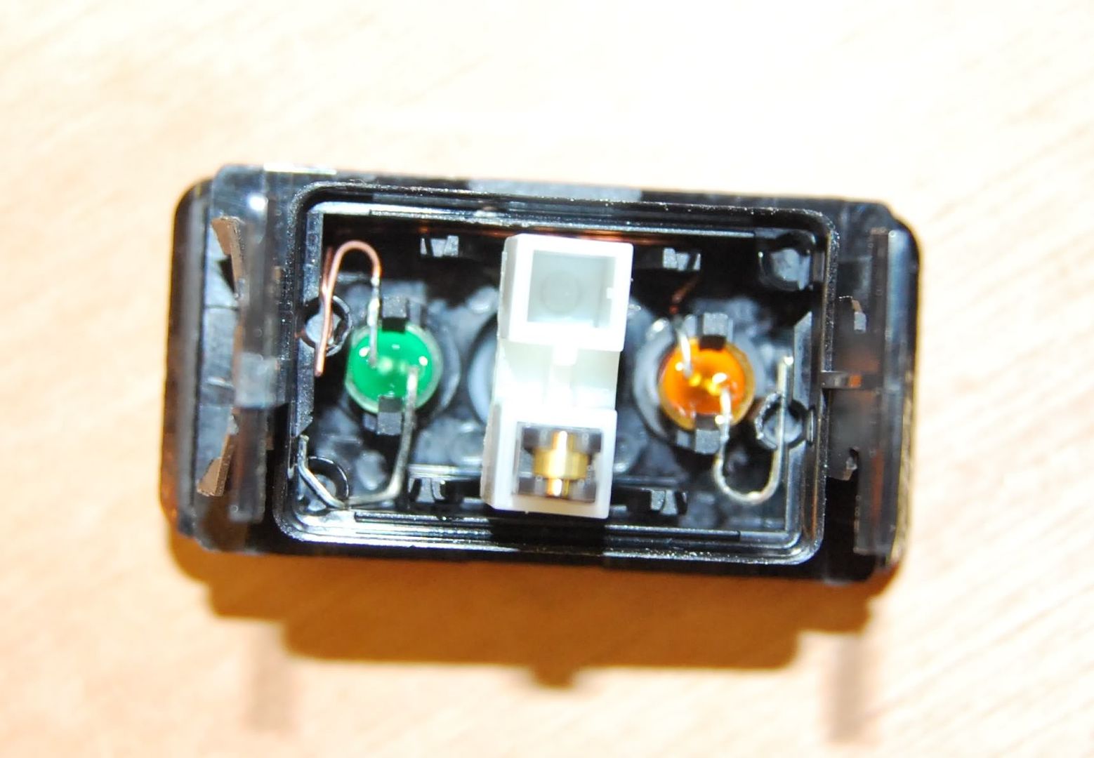
Here you can see the LED circuits in the top half, the silver wires are the positives and the golden wires are the earths. They connect to the base by sitting on pedestals which the springs push on to carry the current to the pins.
Next remove the roller rocker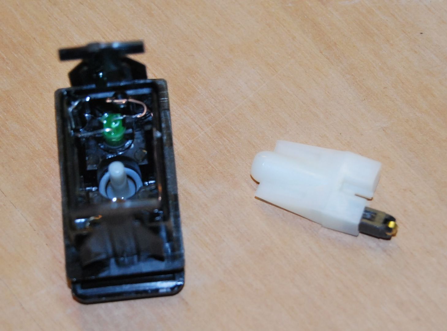
Now we need to move the anode of the indicator LED, bit fiddly, use the tweezers and small screwdrivers to bend it up and away and move it across to the other pedestal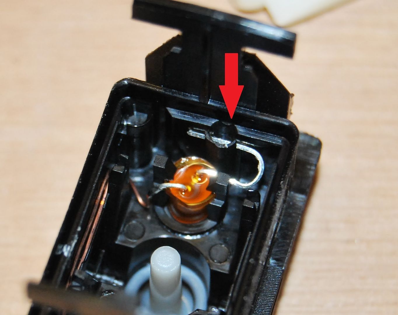
Now put the roller rocker back in and check it has full movement both ways and you havent blocked anything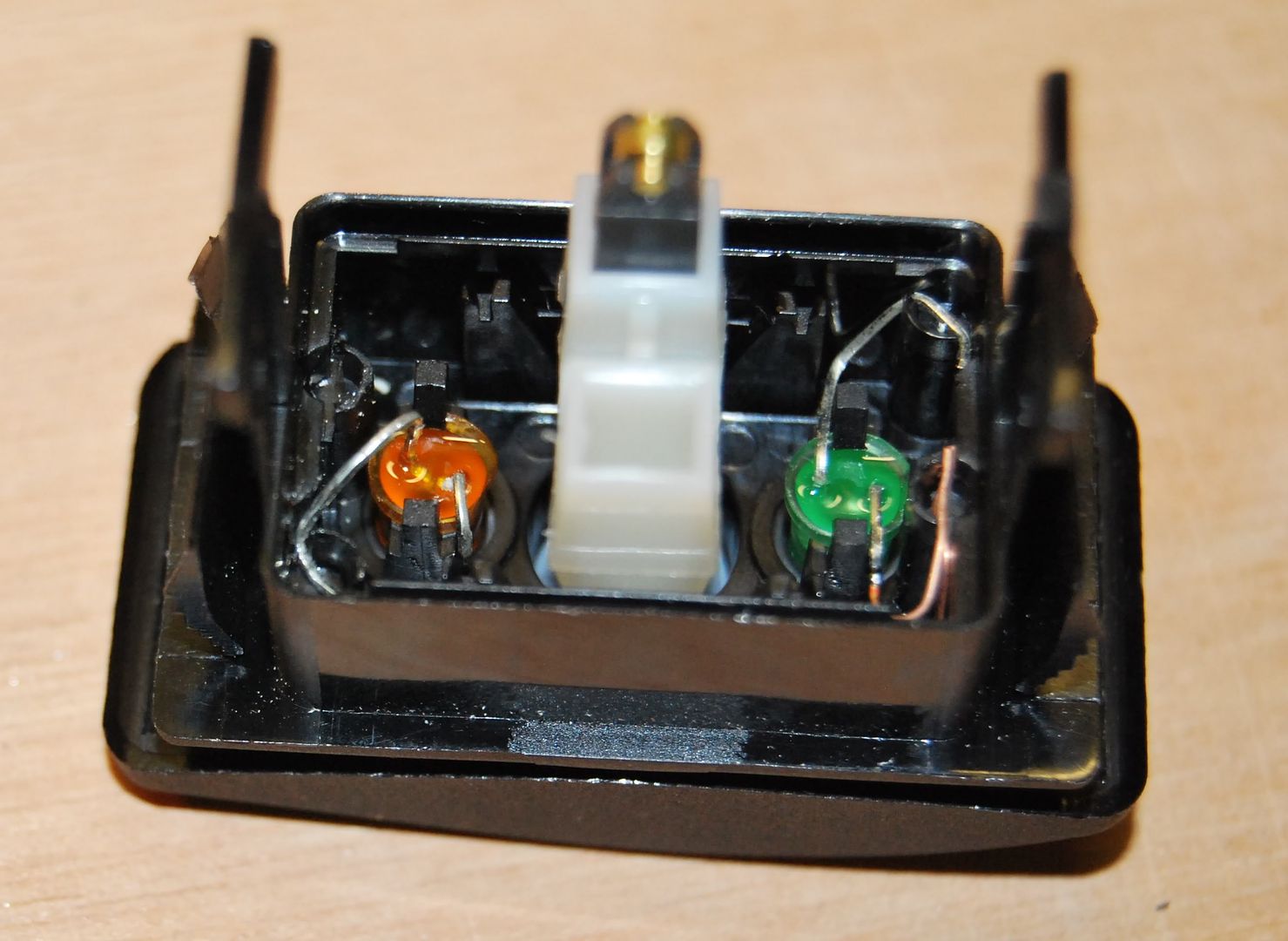
Now move your attention to the bottom half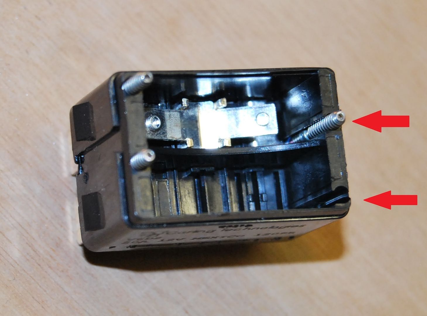
You need to move this spring from the location which takes the feed to indicator LED in the photo to the other half. On a DPDT switch the other half is taken up by gear so it leaves a convenient space to do other things on SP switches.
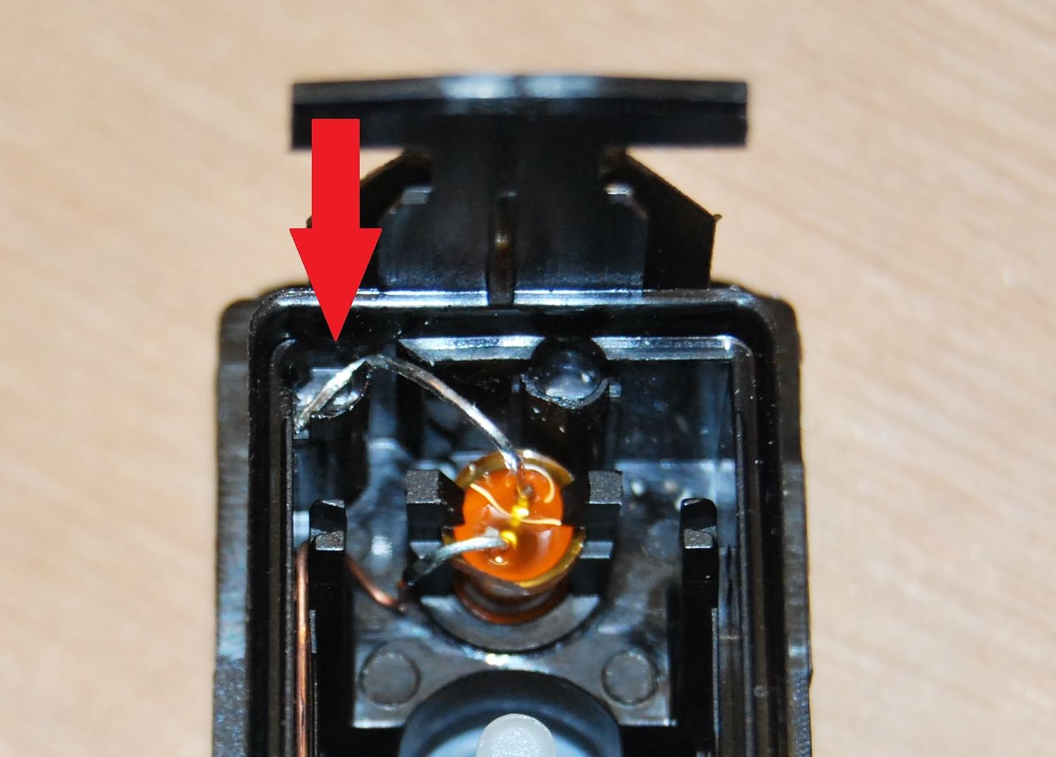
When you remove the spring you will also need to fish out the small cylindrical barrel, this is a resistor, not a diode, so you dont need to worry which way round it goes.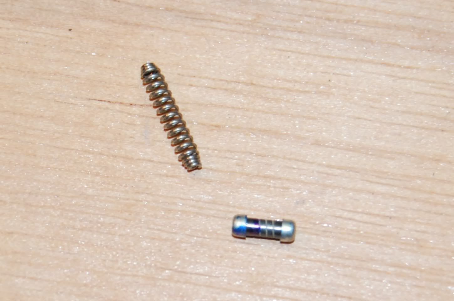
The plan is to drill a small hole next to pin 2 but in the opposite chamber, then run a link wire from the new spring/resistor location to pin 2.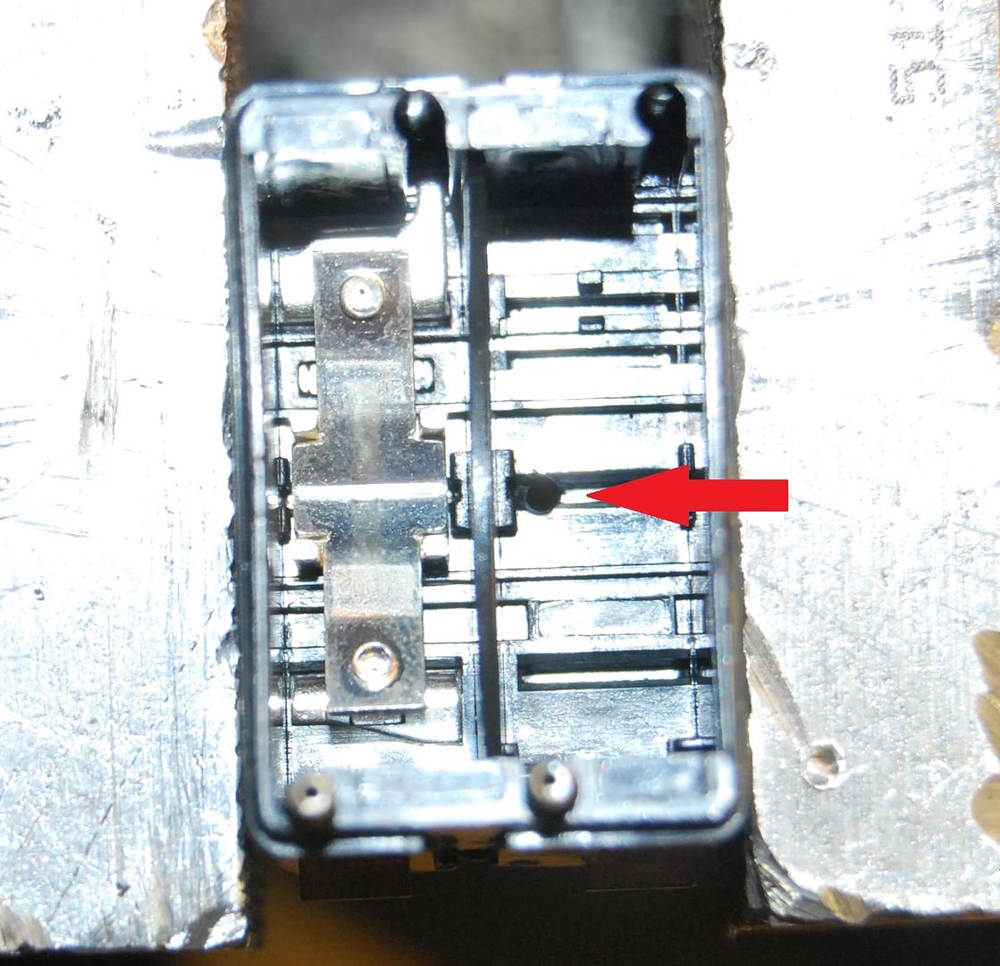
You can just see the hole in the above picture
Now find a piece of wire long enough to go from the base of the resistor through the base and to pin 2, one side of a 1/4W resistor is the perfect length.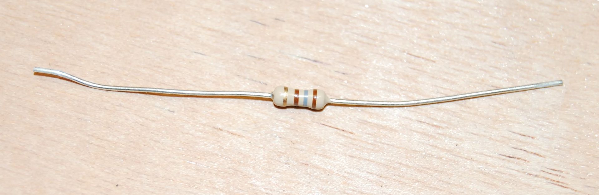
Bend it to this shape to hook into the spring base and go through the hole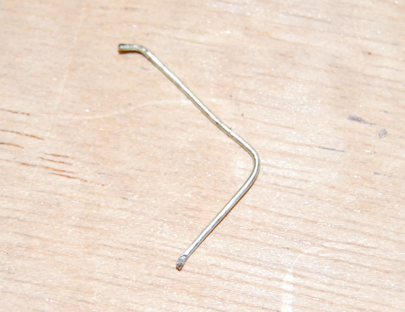
And place it in position with the resistor and spring on top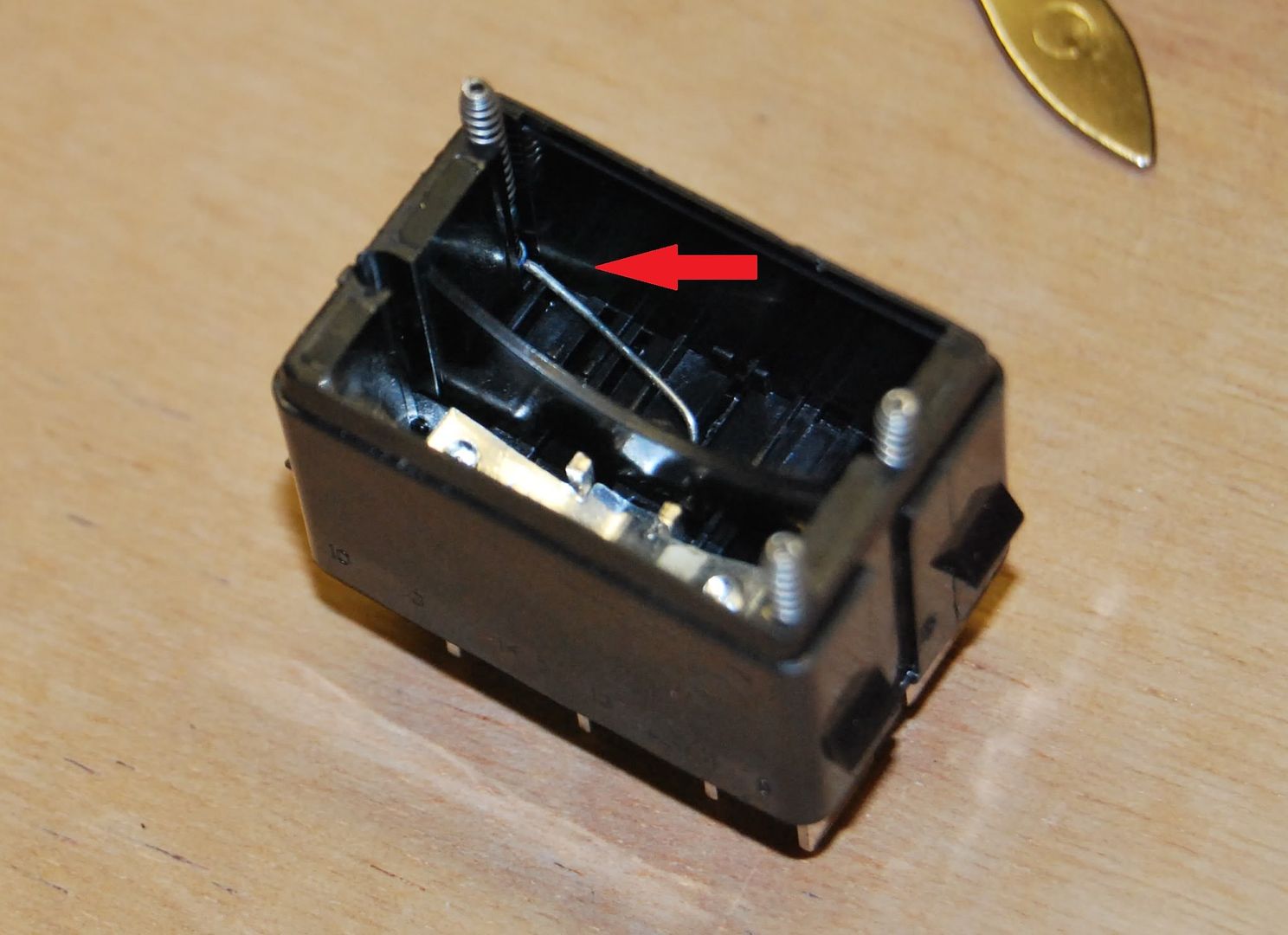
Now you need to put the top back on to put pressure onto the spring to keep the wire in place IMPORTANT NOTE KEEP THE ROCKER AND THE ROLLER ROCKER SHAFT LEFT OUT!!!! Otherwise you will destroy the switch when you solder it!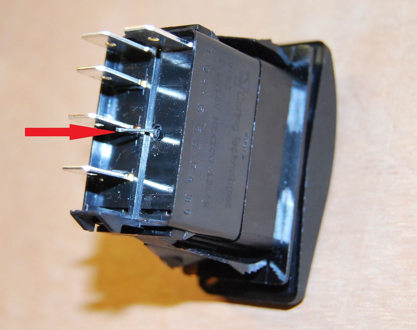
Where the pin comes out bend it down and solder it to the base of the pin, just be careful not to put too much heat into the base, they are well made and as long as you have removed the internal components it should be fine.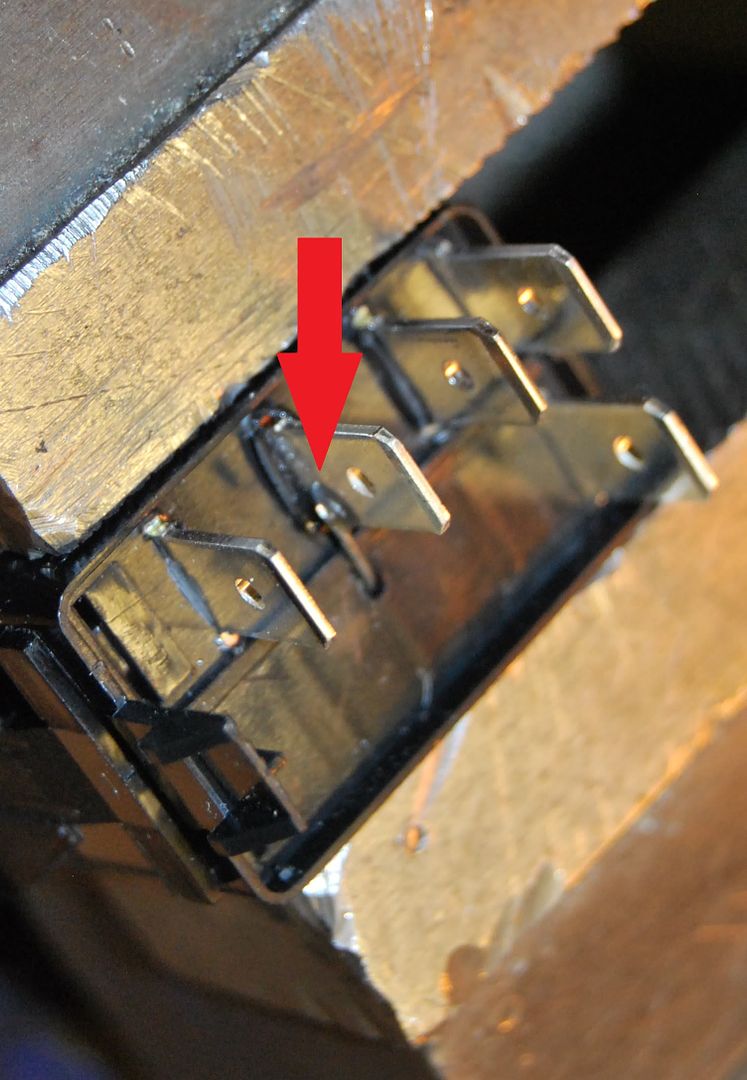
Now take the switch back apart and put some glue on the wire to make sure it doesnt move on the inside and outside, however make sure you use it sparingly and ensure it has fully cured before re-assembly, air cannot get into the housing, so if it goes together wet, it'll stay wet! Re-assembly is the reverse of removal, use the 45 degree trick so it stays together while you push the halves together.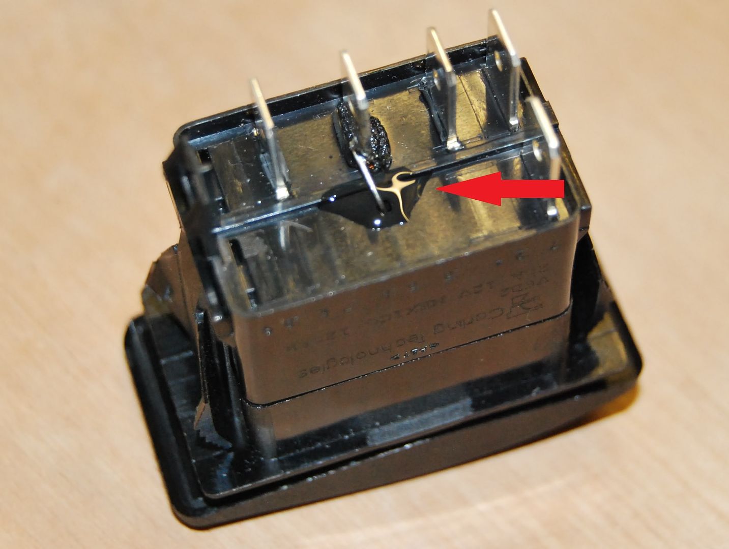
All done, the LED bar will now light up when pin 2 gets a signal and the illumination will work as normal. I do not plan to use the official connector blocks, so I don't know if these will work with the mod, chances are they will but you'll need to add a small groove to avoid the wire.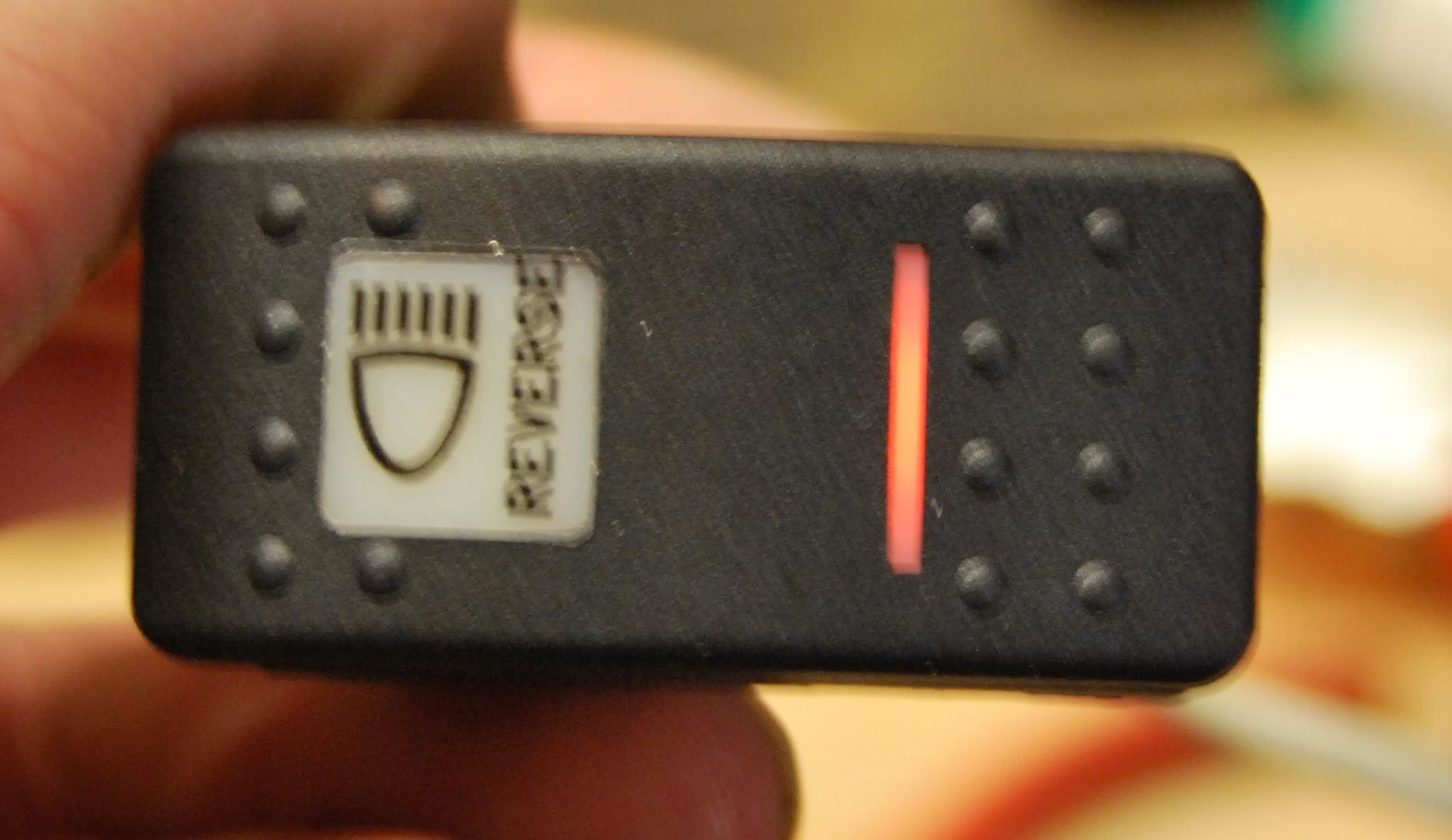
Figured I would do the write up as Im sure more than a few people will want the carling to do something similar.
Ive done it for 5 of my switches Front Fog, Front Spots, Reverse Lights, Voltmeter and auxiliary engine heater.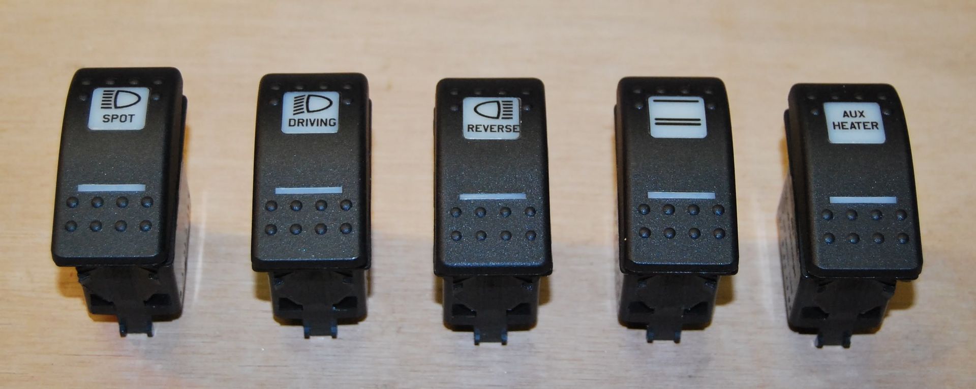
Hope thats all of some use to someone!-
1


I bet this has never happened before! (td5 Help!!)
in Defender Forum (1983 - 2016)
Posted
Just as a heads up...those metal clips do not have to be removed to remove the electrical connectors...you just push them towards the connector and they release.