


Badders
-
Posts
19 -
Joined
-
Last visited
Content Type
Profiles
Forums
Events
Gallery
Blogs
Posts posted by Badders
-
-
I'm with Kevin above... this is really interesting! I need to spend some time looking at what all this means
 , I too have one of Nige's set ups and she pops and bangs a bit, I don't have any timing marks on my engine so it's difficult to time up, I think I did a pretty good job on assembly but I played with the trim this morning and it runs a bit smoother with a couple of degrees in.
Thanks Random_badger

Stu
-
I have to conceed that i may err on the side of caution when it comes to soldering and modding the internals, but now i may have to take up the challenge and go for it...
Badders, if you go down the in-line thermoswitch route, I'm running an 81 degree thermostat with a 92 on 86 off switch, this seems to give a good balance. I know the engine is getting full coolant flow before the fans kick in, I boiled the thermostat in a pan with a sugar thermometer and it was fully open around 85 degrees. Not totally familiar with the THOR layout or which thermostat you have, but would it be possible with a switch that low you may never get full coolant flow in the engine?
I too did the boil in the pan thing... I've got the odd looking thermostat housing, the standard one opens at 92, but i've bought a black one that's fully open at 88 deg, so with my fan coming in at 87 till it's done to 82 it should pretty much cut in at the same time as the rad is full...
we shall see
-
Huh? Are you referring to the knock sensors?
lol they could be Knock sensors... I never paid too much attention, they are there, I haven't touched them.
-
Maybe not the correct one, but it most certainly does! The Bosch temperature sensor is actually two temperature sensors in one. One is used for the dash, the other is used for the ECU.
Ok... yes, not the right one... But with Nige's MS kit you replace it with a different one anyway, it also has a temp sensor on each bank on the sides... no idea what they do but they are sooooo close the the exhausts I can't see them working much longer and for me they are in the wrong place to cut the fan in and out.
-
Just a thought, would it be easier, simpler and possibly cheaper to find a thermostat housing with the switch boss? Seems like a lot of risk fiddlig witht the guts of MS and modding the board if your not 100% confident with the level of soldering. Having had to replace components during my build and then subsequently repairing the damage I caused, i wouldn't risk it agin unless it was absolutely critical. [or am I not getting into the spirit of megasquirt?] I thought about it and went down the thermostat housing route with my trialler as it allowed me to leave a manual overide in place without any risk of affecting the megasquirt. The fan switches are widely available, wiring is simple and risk is negligible.
Just a thought...
I've been thinking the same recently, I have a few extra factors in that the car is a 90 and the engine is the Thor 4.0 V8, My engine doesn't have a temp sensor for the gauge in the dash, so I've already got an in hose sender for that, I don't really want to bodge 2 together,the other factor is that with it being in a 90 they all seem to run hot, so I wanted the ability to set the on and off temps to what ever I like.
All that being said, I haven't heard back from Nige yet, and I can't leave things so I've found on ebay a temp switch that cuts in at 87 deg and out at 82 deg which I should be able to install into my existing in line boss along with the sender, I just need to drill and tap an M16x1.5 hole...
I can't decide if I need a switch on the dash.... it's a nice idea but am I going to switch it off... forget and cook the engine verses spraying some water over a water proofed engine?
-
That's not modded, so has no fan output.
If you're not competent with a soldering iron, send it back to Nige and have it done properly rather than damage the board.
The fan output circuit is pretty simple:

Thanks for this.... I was looking around on the web and had come to the same conclusion.... Send back to Nige!

Competence with a soldering iron is... OK... I think I first used one when I was about 6, I then used one at school, about 14... and these days maybe every month or so, but for electrics not electronics! very very different!
I'm still sending it back to Nige, I know my limits!
Thanks for your help everyone! I have the answer so I can sleep again now!
Stu
-
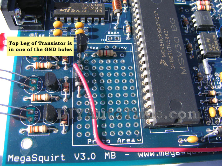
This is the proto area of the board: http://www.diyautotune.com/jwplayer_viral/images/mods/ms1pcbv3-relaycontrol/ms1pcbv3-relaycontrol005.jpg
As above, post a pic, but if that area is empty it is time to break out the soldering iron.
Ok, attached (I hope) is a pic of my board, I was waiting for Nige... but I fidget a lot and my mind goes off

I have PWM and it works great, but looking at this I don't have anything else.. can you confirm?
What do I need to do to get me a relay output onto pin sp3 in the D37 plug?
Thanks for your help
Stu

-
This is the proto area of the board: http://www.diyautotune.com/jwplayer_viral/images/mods/ms1pcbv3-relaycontrol/ms1pcbv3-relaycontrol005.jpg
As above, post a pic, but if that area is empty it is time to break out the soldering iron.
I've just sent Nige an e-mail, better he tells me than I strip the lot out for no reason... I will report back! I may need more technical assistance! like a drawing!
Cheers for your help!
Stu
-
Indeed, I would have thought Nige's units would have this, but very worth asking the Q.
If you open it, you should be able to see the modification on the proto area of the board, just a diode, transistor and a resistor from memory.
proto? from what I have seen online there are a lot of diodes, transistors and resistors lol... how about if I post a pic?
-
Doesn't the ECU need to be built with the proper internal wiring to support this?
I would imagine so... I'll have to ask Nige if this is built into it, might have a dig about for some drawings and have a look inside the ECU


-
Can't help from experience but have you checked to see if the output goes to +12v in respect to ground?
I'm not using MS to turn on my cooling fans so just a thought.
Thanks but yes I tried that,if I stick my power probe onto sp3 and cycle the ignition, the on/off temp, etc I get nothing, I should see a red light for +12V or a green light if it goes to ground.
Thanks for the advice though... It's gotta be summit simple lol
-
Hi everyone
I need some help... I have one of Nige's MS1 setups for a rover V8, but I want to us the MS to switch the fan on and off, reading on here I see that pin sp3 on the ECU D plug is the right output and i've set it up so that it pulls in a relay to power the fan, I have 12V to the coil on the switch and the ground goes back to sp3 pin on the ECU.
But I get nothing... the fan certainly works, using a power probe I can make the fan run, but if i test the sp3 pin it's dead, no ground no connection to anything.
i've tried setting the temp and looking at megatune I can see the output coming on and off, it's going green on the bottom of the screen at the set temp
can anyone shed any light on what i'm going wrong? is there some setting in the ECU to make this active or something?
taaa
Stu
-
I soooo wish I'd seen this thread a few weeks ago, I've just got a 4.0 Thor out of a disco 2 running in a 90...
She's not on the road yet but it's getting close and I'm looking forward to it
Stu
-
Hi everyone,
I'm pretty new on here, I just wanted to say Hello
I've got a 300tdi 90 which is soon (hopefully) to emerge into the world as a 4.0L Thor powered V8, I got the engine out of a Disco II
Does anyone know of any other Thor V8 defenders about? I'm keen to hear about how they got on!?

Stu
-
Do you only see 150rpm in that case, or is it possible you see another rpm?
I was seeing the cranking speed in Megatune either way around, but I was not getting a ground at the coilpacks. I would see 130ish rpm if the battery was a little flatter or 155 ish after a full charge...
I fear my battery is on the way out too!
Stu
-
-
Ok, I've had a bit more communication with Nige and it's sorted!
it turns out that even when the VR is around the wrong way you can still read rpm on the laptop... turned them around and off she went!
Stu
-
Hi Everyone
I could do with some help please?
I've bought a MS kit from Nige but I need some fault finding help, I have the kit installed on a Thor 4.0 from a disco 2, now mounted into a 90, but I can't get it to start, I've done a few tests and the coil packs aren't firing, with testing I have 12V to the centre pin on the LT connector on to the coil pack, but I'm not getting a ground whilst cranking... on any of the 4 coils.
My laptop is reading RPM of about 150rpm during cranking, so the VR is working, the injectors are firing, I have water temp, air temp, MAP pressure, Throttle position, but no spark.

I have a friend who's a similar set-up so tested my EDIS on his car yesterday and it worked fine...
I have continuity from the coil packs to the EDIS, every other wire looks to be correct, I even disconnected the PIP ans SAW wires after reading that the EDIS will go into limp mode if they're not connected... nothing!
the EDIS was earthed out to the battery, but I've just changed that to earth into the MS ECU...
I know it must be my wiring but I cant find it... and even if I did have the coil pack wires in the wrong order I should still have coils firing, even if it won't run?
Thanks for your help...
Stu
 , I too have one of Nige's set ups and she pops and bangs a bit, I don't have any timing marks on my engine so it's difficult to time up, I think I did a pretty good job on assembly but I played with the trim this morning and it runs a bit smoother with a couple of degrees in.


MS1 Radiator fan control problems
in MS-Megasquirt/Jolt
Posted
Not as yet, I currently have a modded e-bay temperature switch housing which has a sender for the temperature gauge and now a switch for the fan, it's cutting in about 88° and currently doing a good job, I've not seen temps over about 91° when in traffic...
I think I will get the ECU modded to though. I'm currently having PWM problems, in that it's not working (and i don't think it ever has) so once Nige gets back to me I may kill 2 birds with one stone.
Stu