


CountryGent
-
Posts
222 -
Joined
-
Last visited
Content Type
Profiles
Forums
Events
Gallery
Blogs
Posts posted by CountryGent
-
-
The push rod stays where it is as it's attached to the clutch fork with a little clip so it won't pull out. If you do pull it out, it's a hell of a job to get it clipped back !
Your new clutch slave won't come with a push rod, you just slide the new slave onto the push rod through the rubber boot.
HTH
Mo
Yep helps BIG time as I have learnt that that proper name is a push rod and that I most definitely won't be taking it out unless I want a lot of unnecessary work!
Thanks
-
Hi,
Whilst under the 110 fiting the new exhaust I happen to notice that the clutch slave cylinder looked loose..
So I went to tighten the cyclinder and the lower log was bolted in but the lug had cracked off so I removed both bolts and took the cylinder off. Now I had expe cted the whole assembly to come of as one

Well here's what I was left with:
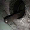

Now because I didn't want to damage something I don't know about I have only had a gentle attempt at removing the shaft but seems very well attached - that is to say STUCK!
Can any body tell me the right way to remove it without damaging and breaking something else that will need replacing..
Any help greatly appreciated!
Thanks
CG
-
I'll second what you say Retroanaconda . I have a Rebel steering guard with built in recovery eyes. Not too happp about the sharp edges but that makes me use a shackle.. With the Rebel guard the recovery eye is held to the chassis by three through the chassis bolts either side.
At the rear I use a Southdown tank guard with the rocovery eys. Again the mounting bolts are spread about the rear of the chassis.
Don't throw the laashing eyes away. Keep them for lashing and for the sacrificial rope when recovering.
Yes the steering guards I will be looking at once I have the 110 roadworthy. I really like the spec and look for the Southdown tank guard - especialy the removable tow bar..
Thanks
-
The tensile strength of the bolts isn't so important in this application as the force is in shear. The weedy thin metal of the chassis should tear out long before you exceed the shear strength of the bolt. If you want to fit recovery points to these areas then use the proper cast JATE rings, as they're a lot stronger than the aftermarket welded ones.
However I have found that these areas aren't ideally located for recovery points. They're about strong enough (though mine did elongate the holes in the chassis on some harder pulls), but being so low down they tend to be in the mud/water and therefore a pain to get to! I would recommend some bumper-level recovery points such as those incorporated into steering guards, or rings/hitches that bolt to the rear crossmember.
Thanks for the information on the forces at play when using the recovery points. I intend to use the type of bumper level recovery points you mention as these seem to be the most useful.
Cheers
-
As long as they are 8.8 rated they will be fine.
Cool...I think what does the rating 8.8 relate to mean?
Sorry but still trying to pick up the knowledge along the way..learning something new every day is good

-
id reccomend using high tensile bolts you would get away with average bolts, but if you go to the right suppliers HT ones are not much more expensive and if you snatch them there much more likeley to survive.
Thanks for the advice
-
Ok as I plough through the seemingly endless bits on the 110 conversion I have a question that's not directly related to the work.
The question is that I want to replace the tie/lashing eyes front and back with some recovery points. First thing that I want to know is a simple one, do the bolts have to be high tensile (I think that's what I mean
 )? Where do I get some if so and what size/length etc do they need to be?
 Then the next one is (based on my VERY limited criteria..currently 'they look' good) I am looking at fitting something like these: http://www.extreme4x4.co.uk/acatalog/copy_of_SWIVEL_RECOVERY_EYES.html
They seem good quality and a decent price which I always like!

It is just a way of incentivising myself and preping the 110 ready for the winter so I can pull stranded BMW X5/X3 Audi Q7's etc out of ditches, drifts etc

Thanks in advance
CG
-
Well it's been a long time but I am going to start running out of time soon so I need to get cracking on finishing my 110 conversion...
The question I have is as result of losing the pipes from the donor D1 when it went to the scrapyard in the sky..I thought I had put them some where safe but had left them in the truck!

So I have fitted the power steering box and pump into the 110 but need to get new pipes made up. Not a problem, I have the lengths I want but I don't know what connections are needed on the pipes that connect to the steering box and the pump..
So what details do I need to give to give to resolve my stupidity

Thanks in advance
-
does it look like these red & black battery cable terminal covers
or any of these Autosparks
cable end terminal covers are not shown as seperate parts in LR parts book, normally come pre-fitted to the genuine cable supplied by LR.
Great Ralph just the kind of thing I'm after - the red & black covers look very similiar. I shall go and part with hard earned very shortly!
Thanks for the help really appreciate
CG
-
Ok I will now demonstrate my complete lack of technical terms and knowledge relating to engines. As I am doing my engine upgrade I am fitting new parts where required. When I removed either the starter motor or alternator and had what I can only describe as a terminal cover cap. I can't remember which it came off of bit it had certainly seen better days - literally fell apart when I took the leads off. I would like to replace but have no idea idea if it's specific to either the Starter Motor or Alternator or if some one added it as a way to protect the leads and terminals from the mud and crud that gets thrown up off road.
Any help appreciated - the engine it came from is a '93 200Tdi Discovery engine. If it's not a Landie part a name of what ever the part is called would be great so I don't look like an idiot when I try and explain what I'm after in a motor factor

Thanks
CG
-
I have finally got the last few parts I need to fit the fly wheel casing I got from Les (thanks
 ) the gasket and the fly sheel seal. The fly wheel housing I have now is a N/A/TD and dry fits perfectly to the bell housing with one stud removed from where it doesn't have a hole - just by the clutch slave cylinder. However I have noticed that the drain hole rather than being at the bottom is on the back. I guess with the N/A or TD engines you would have space enough to fit a wading plug but as it's fitting onto the 200TDi Disco block there is virtually no gap. Does this mean that I need to fill the original hole and drill a new one on the bottom?
 If so what size are the drain/wading plugs and what size do I need to drill and tap? or is there a way of fitting a wading plug to the original hole once the engine is installed?
Thanks in advance
CG
-
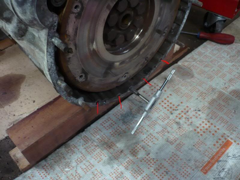
Here's a picture of me tapping holes for some extra studs.
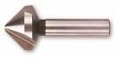
I countersunk the holes marked in red, with a drill (20.5 mmm) as shown below:
Mind you, if there is an easier/better/original way I'd go for that, I was advised to buy the Steve P. bolts and went ahead...
Great pic thanks. Looks like a nice clean garage/workshop! Lucky you - I'd kill for a dry place like that rather than the mud pit that I like to call home
Think as Megansfolly suggests I'll go the original route and see if I can my money back from SP!
Cheers
CG
-
why not just use a NAD or TD one saves all the pratting about
Er that sounds much easier - especially if that means me NOT damaging the housing by drilling some thing
out...
Thanks
-
Hi,
I'm sure Les and Western will help you out with the missing studs.
As for the extra 4 fly wheel house bolts, yes you do need to countersink the wholes in the housing (if you are using the Disco-fly wheel housing and the original bellhouse on your TD/NA gearbox)
But you need to countersink the wholes on the inner side of the fly wheel housing, the side that mates with the bellhousing.
I bought the same 4 bolts from Steve P. and they came with some counter-sink instructions.
Not that difficult if you have the proper drill.
Great I guess I'll have to get the details from them as I din't get any

Thanks for that
-
Which flywheel housing are you using?
Les.
Hi Les,
SHould have said it's the Disco1 200 TDi
-
Ok so I am doing the conversion on my 110 and have almost got to the stage of fitting my nice and as clean as it's going to get engine into the bay. I have taken the fly wheel housing off and cleaned it so I can offer it up to the bell housing. On placing it against the bell housing I was relieved to see that it will fit - yippee!
How ever one of the studs - one that would go through the hole by the clutch slave cylinder if ther was one!  won't go through for that reason. Does this mean that I need to drill a hole as if I do there is no way to put a nut on it as it would effectively be in the bell housing

Then there is the small issue with the fact that there are only six studs around one edge (including the one with no hole to go into). How ever as part of the various parts I have bought to assist me once I start putting the engine in I have some parts from Steve P. Some of those bits are four fly wheel housing bolts with counter sunk heads. How ever I can't see any counter sunk holes but at the bottom of the housing there are four holes which could be used but again if I they are to be used do I have counter sink them? Or I am doing some thing completely wrong?
Here are the four holes -

Here the four bolts in 'place'?

In case it hels any here's the housing front view -

Any help greatly appreciated to save me going mad!
Thanks in advance
CG
-
2.5 n/a diesel & Petrol & TD & 200Tdi metal engine mounts & the rubber blocks are all common parts to those engines.
Great. Thanks Ralph for the confirmation at least I know I now have a source for the brackets

-
Gavin,
I suggest the usual tool loan store in Trowbridge, I have a set of rubber mounts and brackets in my collection. They would have come off a 2.5TD, but I think they are the same for the 200Tdi (It's too dark to go grovelling under my engine compartment now!). Can someone confirm or deny?
Cheers
Peter
Sounds great - I have the rubber mounts ordered so they will hopefully be in for me to collect tomorrow. The brackets would be good though. Will cross your hand with beer tokens.
Thanks
CG
-
Ok so there I am happily doing my conversion (see 110 conversion) and have just completed doing the suspension and lifted out the engine ready to mount on new STC434 mounts when they turn up. So as the engine is out I thought I'd take of the D1 mounts and put the mounts off my 2.5 N/A engine on. Well imagine my suprise when I couldn't find - I think after I took the engine out of the 110 I took them off then put them back so I knew where they were but forgot to take them off when I sold it!

So can I modify the Disco mounts as they appear considerably different to the 110 mounts or am I going to have to buy a pair to replace the ones I er sold!? If I do have to buy a pair...whose got a pair that they want sell me at a reasonable price?
Thanks in advance
CG
-
I've probably got a set here if you want them - you're not that far from.
Les.
I'll see how I do with the chains and if it looks like I'm going to do any damage will come over to you for the rings.
Cheers
-
I found it was difficult to get the right tooling in place to remove the nuts when I did my disco conversion. So i took a 9 inch grinder to the downpipe removed it right up to the nuts then had nice easy access to it
Excellent idea..will do some grinding to give the improved access.
Cheers
-
I'd use a proper penetrating oil as well, like Plus Gas or something similar. WD40 is a water dispersant, better than nothing but not as good as the real thing.
Supply of plus gas purchased. Thanks for the idea.
-
Lifting eyes are both on the head -
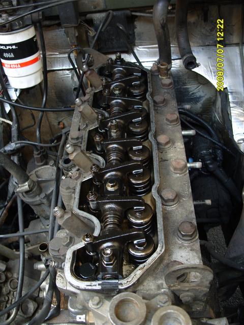
Les.
SADLY MISSING
-
I did this just recently, one came off ok, the other I cut the exposed end off the stud (so you are not running the nut over a rusty thread) and I found that some heat from a blow lamp helped with the last one.....which actually brought the stud with it.
The nuts themselves look like a lock nut that have no thread on the very end and so cut a thread as you tighten them, this doesn't help when you come to undo them; however it does stop them coming loose due to engine vibration. Anyway I digress.
To remove the studs, clean up the thread, I used a thread cutting die. Then wind on two nuts and lock them together. Use the inner of the two nuts to undo the stud from the manifold.
As for 200Tdi lifting rings. There should be one on the front middle of the engine and on between injectors 3 & 4 (IIRC)
HTH
Wow sounds good but I will have to improvise the heat side of things as the closest I can get to that is my wifes hair dryer and I don't think that it will generate the kind of heat you're talking about!

I think I can do the lock nut side of things with the guide above.
The lifting rings are sadly MISSING
so I guess I'll have to see if I find/borrow some as I can't make any..not yet any way
 )? Where do I get some if so and what size/length etc do they need to be?

Clutch Slave Cylinder
in Defender Forum (1983 - 2016)
Posted
I won't pull the rod out !
I won't pull the rod out !
I won't pull the rod out !
I won't pull the rod out !
I won't pull the rod out !
I won't pull the rod out !
I won't pull the rod out !
I won't pull the rod out !
Just as well I asked!
Thanks