


Lara
-
Posts
889 -
Joined
-
Last visited
Content Type
Profiles
Forums
Events
Gallery
Blogs
Posts posted by Lara
-
-
Hi Gremlin,
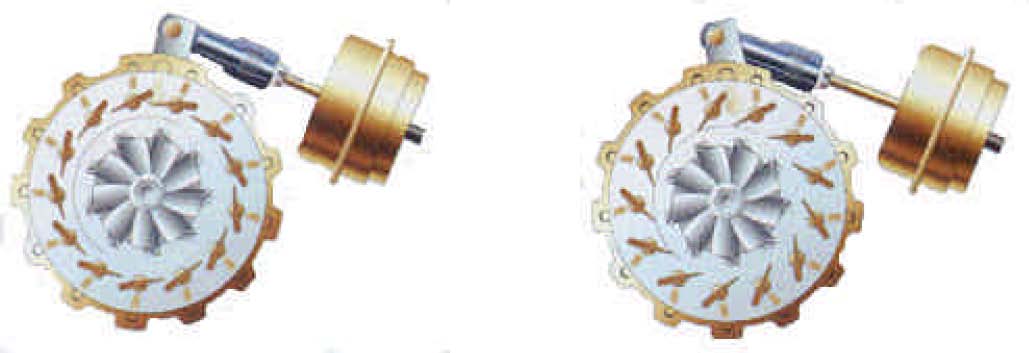
sure, All I did was to use a standard type boost controll capsule and fit it to work in the oposite direction to the vacuum controller, ie. to push instead of pull.
Work out on whatever unit you use what direction you need your actuater to work in. (Vanes need to be closed at low boost and open as boost increases) and rig up your boost controll to work appropriately. Getting the correct spring pressure takes a little doing as it is not the same as a wastegated unit.
I split one of my old units at the seam and made a clamp ring to bolt it back together again so I could change springs at will. One days messing will usually sort it though.
Hope that helps.
Pic here to show vane direction. Low boost setting Opening as boost increases
Lara
-
Without a doubt in my opinion (25 years playing proffecionally with modified engines and Turbos) the best turbo to opt for if you are going to play DIY installations is the Garrett 2559v from something like the Renault Vel-Satis etc These have the larger 25 series water cooled bearing housing and can stand higher sustained throttle openings without bearing problems etc. I was one of the first people (about 2004 surely not the first though) to fit a VV turbo to a TD5 engine and after much testing I found this unit to be far and away better than anything else tested. Initially this was fitted to a 2.5 litre engine and later to my Stroked 2.8 litre TD5 engine. Ultimately giving 265(real)bhp and 420 ftlb torque @ 1900 rpm. with a JJ Fearn chip and 2 Bar boost. Although this was rather too black for road use to be quite honest.
Try using a 2559v you won't be disappointed. !
Just bought another one myself to fit to my 110 Overlander.
A Variable Vane unit working correctly will be one of the best buys you can make for Landrover fitment! Total transformation!
Lara
PS. I use a modified pressure type progressive controll similar to the units on wastegated turbos, simple and reliable.
-
Don't tell me Steve,
You were getting "Work" hardened, and as nothing KAM ever made seemed to be hardened, you had to go!

Don't answer that! am taking the "P"
Good luck whith whatever you are doing now!
Lara
-
Don't worry folks!
Devon are updating as you probably know and there are a few issues with the new site etc that need to be sorted out!
All will be working again in a very short time!
Lara
-
I dont recall replacing a u/j in the last 5 years.
Daan
Christ Daan!
Surely you can try harder than that!!
-
Good link!!
I have to explain this to clients on a regular basis. Now I can just post them the link. Thanks!
Lara
-
Pressure in fluids is simple physics - you are trying to convince us the physics that has been taught for hundreds of years is wrong

If you can't understand the physics and how the pressure in the crankcase acts upon the surface of the oil in the sump and adds to the hydrostatic pressure at any depth in the oil, then have a look at how a basic mercury barometer works - how atmospheric pressure acting on the surface of the mercury changes the pressure in the mercury making it rise, thus becoming a measure of the atmospheric pressure.
At any depth below a static fluid level, the pressure is equal to [ (fluid density x depth of fluid above that level x acceleration due to gravity) + pressure acting on the fluid surface ]
Hi Bushy,
I don't think that anyone is saying that the physics and theory are wrong.
What is actually happening in the system described is difficult to know for sure but it does work. So somewhere in the line something has changed in order to make it work. That is fact, but "What" is the question!
I think this.
In your barometer example you have a higher pressure acting on the fluid, forcing the fluid up to a lower pressure area. Natural physics. You have a sealed capsule on the top with 1000mb pressure and varying pressure on the base fluid, so creating a moving column.
In the engine, I think that the pressure above the sump oil (vented to the catch tank) and the pressure inside the return pipe dipped into the oil (also vented to the same catch tank) will stay the so close as not to matter. (maybe enough to raise the oil in the tube by an inch) a pressure difference of enough to get gas flow but not a lot else unless we block the other vent to the crank case!
If we leave it like this the oil in the catch tank will drip down this pipe. and the level will equalize with the new level in the pipe.
If we have the drain pipe above the oil level, the pipe will be subject to airflow, (just as the main scavenge pipe) thus carrying with it small droplets of oil that may want to go down and thus hampering the effectiveness of the drain tube.
I have used both systems and they both work, however the system with the tube returning below the oil usually spits less out of the catch tank breather than the other, and keeps the tank empty even at full throttle max revs, where as the other works less and less efficiently the higher the engine breathing! but perfectly at lower revs / loads etc.
However,
With the drain below the oil level,
I have also seen on engines with damaged rings and or holed pistons etc, the oil getting blown up this tube like a fountain!! we do need to treat each case with care and thought! We would not want this on a Diesel

Lara
-
I agree with both of you!
In theory it should,t work like it does,
But in practice the fact that there is only a relatively small pressure in the crank case and not enough to blow the oil up the pipe if fitted below the oil level, this in turn allows the oil to run down the pipe, unaffected by the airflow it would normally encounter if above the oil level.
In practice it does work quite well as Zoltan says.
Lara.
(not 100% sure on that theory but it's the only explanation I can find) and I was on top of the world at the time looking down on my creation!

-
Into the cab heater, so on hot days you can smell how good your engine is breathing
Lara
-
Lara,
Are you advising that the catch tank is just naturally venting and there is no need to pull vapour through the vacuum system and back into the plenum?
Neil
Hi Neil,
No not recommending it in this instance.
I would agree with Aragorn about the water issue!
However on a race engine you rarely plumb it back to the inlet as oil can contaminate the inlet charge and cause detonation, because generally if building a race engine to it's best potential you would be running the highest RC possible to get away with given your rules and regs and fuel available etc. It would be unwise to let oil get in there!
Actually, the clever racing guys sometimes plumb it into the exhaust in a way to use the exhaust to create a negative pressure and suck from the tank! Not so easy in reality though and you need a very free flowing exhaust system for this!
Lara
-
I find this material very effective!

Lara

-
Yes I agree with that one!
It looks far too small.
It is actually one hell of a job to make a good shaped catch tank that does not blow oil out the top under race conditions when your engine is "breathing hard"
Nige
Top pipe is breather to filter box or for a separate filter etc,
Side pipes are inlet from engine, either both rocker covers or crank case inlet valley and rocker cover, but would suggest both rocker boxes! Also if you rivet a small plate over the inside of the fittings in the rocker cover, these will act as "splash deflectors" and stop the rocker gear throwing oil into the pipes!
Your tank hopefully has extensions to the "IN" pipes on the side that turn 90 degrees and point them down. If not then cut a saw slot across the width of your tank, vertically down and at 90 degrees to the inlet pipes, from the single "OUT" pipe fairly close to it and on the side of the inlets and going down to about 10mm past the bottom of the lower of the two pipes. Then insert a piece of ally sheet cut to size and weld shut again. This will act as a reasonable baffle / deflector for the oil particles suspended in the "breathing" air. (I am trying to describe a plate shielding the inlets and outlet)

How is the build going?
We are all excited!
And out of interest, how much is it costing?
I remember years ago building a few 4.6 litre engines for F2 Ski boat racing, and parts made it rather expensive. I would be very interested to know if things had changed? Everyone always quotes the negatives of your type of build as too expensive compared to yanks etc but is that still true?
Regards,
Lara
-
May be interesting or not
But a couple of years ago I did some load cell tests of a few winches and motors etc and found a massive difference in efficiency between winches that were supposedly the same and even fitted with the exact same motor (actual motor from the other winch) and treble checked for repeatability and comparability!
I mean over 25% in some cases (forgive the pun)
I think you would need to test the motor directly to get any real figures!
I would make up a disc brake with the calliper connected to a load cell and calculate from there!
Hope comments are of some help.
Lara
-
Hi again Richard,
Just re-read my reply and just want to say that my response was difficult to word and I mean no disrespect what so ever.
I am just trying to put over my findings from many years hard dedicated work and learning.
I too may have made mistakes but am fairly sure there are no serious ones above!
(other than the odd spelling)
Best regards,
Julian
-
Hi Richard,
Slightly more understandable but just to check my understanding of your Ford PCV description. You are saying the vacuum on the filler cap was with the venting pipes "Still connected"? if so I agree this is quite feasible!
I totally disagree though with your theory of Diesel efficiency being to do with its density!
As the energy BTU/lb or Kj/kg of diesel is very similar to petrol, Approx 19000 compared to 19300btu depending on ingredients which varies more for petrol these days than Diesel, so to be generous we are talking 1.58% here! not a staggering improvement really!
lb for lb will show you that it has almost nothing to do with the density of Diesel fuel.
That is why at WOT power for power there is not much in it fuel efficiency wise from engines of the same size / mechanical and volumetric efficiency rating. however at part load etc and general driving round town conditions they are vastly better due to the reasons quoted, and also due to the fact that in general and other than racing use diesels are always in a "Lean burn" condition and regularly run with 50% or more excess air. A condition not advisable in a spark ignition unit. It is though a little hard to compare the two as they are never "like for like"
I am very well aware of BMEP and know the theory quite well. You will also see that a Diesel at lower revs has a very high BMEP and this directly relates to Torque.
Theory as follows. BMEP = (Torque x (12 x 33,000 / 5252)) / (Displacement in Cu/in x 0.5-for a 4 stroke)
So you will see that an engine with more torque will have a better BMEP than one with less. (Size for Size)
*note, the 12 x 33,000/5252 is normally abbreviated to 75.4 but I wrote it as above to show workings.
As you can see that higher torque = higher BMEP you are actually telling me I'm correct.
This statement below is fundamentally wrong which ever way you read it!!
"Diesels, hmm, whole different issue. Until the introduction of the "clean air act" diesels none of them had inlet manifold vacuum, or more correctly plenum vacuum, because there was no throttle plate. So unless you have a vacuum pump there is no way to absorb the piston ring blow-by with a PCV system, there is no positive ventilation. On turbo engine there is perhaps some vacuum ahead of the turbo when the engine is on-boost but I suspect the location of the breather elbow is more about not allowing the indirect emissions out to atmosphere."
Vacuum is not a condition of which fuel is burned!
Vacuum in a Diesel or in a spark ignition engine are identical all other things being equal!!
The inlet manifold vacuum below the butterfly does change yes but not engine vacuum total! Both suck just as hard from their relevant air filter boxes!! Turbo or not!
Let me explain the theory.
Both engines are 2000cc 4 stroke engines.
Both have the same static CR, (not that it matters here much)
Both have the same Volumetric efficiency, (for arguments sake let us pretend 100%)
One revolution = 1000cc sucked (or blown if you really want to be pedantic) into your engine!!
It is not until ignition that the engine finds out what it is! and reacts accordingly. (simplified here ;o))
Lastly,
Please don't go quoting your Dr's degree expecting me to fold flat and collapse!
A degree is a piece of paper! We all have them, just as I have my Engineering degree, it is also a piece of paper and I know now a trillion times what I knew when I got that 25 years ago. And most of my non degree colleagues know more also!
It does not stop me being wrong and it does not mean I know any more than the next man. that is the fun of life! You never know who you are talking to or what they know!
You only ever "know" that what you know is never enough!
When you say on one hand "Dr" AND "Internal Combustion Engine Theory" And on the other you are not aware of "effective Compression Ratio" then I have to ask whether this was a quote from something you read or are you actually a DR of internal combustion theory?
I really do not want to sound condescending but this really is basic of basics here! I find it extremely hard to believe you research internal combustion engines without knowing this!
The "Effective CR" is as follows and put very simply,
An engine with a static CR of 10:1 that only fills it's cylinders by 50% due to poor efficiency etc has an "effective" CR of 5:1
As can be seen, you can give your poor volumetric efficiency engine a high static CR and have the same effective "actual" CR as one with a lower static CR but better volumetric efficiency. Therefore this is the "ONLY" CR figure that is relevant to anything!
As we know and can test and can see above,
Diesel engines have extremely high cylinder pressures compared to spark ignition engines of the same type and size etc. this is generally why they breath more!
The main reason Diesel engines have difficulty revving is for the following reasons, in order of importance.
1.As Aragorn states quite correctly, The flame propagation rate of Diesel during the injection. (if it does not burn fast enough you can not inject it without causing other problems) this limits #2 below.
2.Injection time available, You need to inject the fuel at the correct time in order for it to burn and reach it's peak cylinder pressure just before TDC otherwise you end up with a poor efficiency and over heated EGT etc. as you can imagine, these are serious limits (the development of modern fuels and extremely high pressure injection systems has given us a big increase in high speed diesel engine availability in recent years but we are still limited)
3.Weight of internal components to withstand the higher cylinder pressures compared to petrol engines.
4.Stroke etc is currently one limiting factor but a diesel does not "have" to have a long stroke!
Enough for now, I need to do some more work!
Lara
Engine development, thermodynamics research, mostly but not always related to the internal combustion cycle have been my life for the past 30 years, Full time working and hobby! and I can also get things wrong sometimes! even without my degree

Theory and Practice.
-
With regard to the old cross flow mentioned above, Ford fitted several variations of "positive crankcase ventilation" depending on engine size and model year.
The larger engines fitted to later MKI and MKII Escorts used an oil separator mounted on the back of the crankcase above the back end of the camshaft (which does throw oil into the separator).
The separator was designed to be cleaned every 2 years, it had internal baffling to remove the bigger drops of oil, the other end of it was connected to the inlet manifold via a non-return valve. This protects the crankcase in the event of a backfire.
The basic idea is that at part throttle the vacuum generated by the engine was greater than the pressure caused by piston ring blow-by so that the oil vapour and combustion by-products in the crankcase could be burned by the engine to improve emissions (indirect emissions I think was the phrase). A secondary benefit is that the crankcase runs at partial vacuum which protects the oil seals when running at medium throttle/high speed such as cruising the motorway. Correct!
Air is drawn in through the filler cap which had a scrubber built into it, the air passed through the rocker box down the pushrod holes into the crankcase. You are contradicting the above correct statement here. The air goes the other way. The crank case does not and can not breath in! unassisted. (unless due to sudden cooling etc)
At wide open throttle it was possible on worn engines for piston blow-by to overcome the lower vacuum and the engine would begin to breath out, conversely a good "tight" engine would exhibit a powerful vacuum at the filler cap whilst idling.
Try it! And ask your self where would this "Vacuum" come from? That is why the PCV system was invented! All engines breath Out due to piston ring blow-by, Some more than others though
Or maybe I misunderstood what you were saying?
The system employed by Rover was not quite as successful. There are several incarnations on PCV system but the later system employed a filtered inlet breather on one rocker cover and a "flame trap" breather on the other (opposite the oil filler which should be air-tight). The oil vapour is delivered by a T piece to both the plenum and the throttle body. Unfortunately this means that the crankcase is never under any significant vacuum, on a new engine the breather system by-passes the throttle plate and if broken it can affect idling.
Catch tanks are often fitted to allow the removal of the PCV system. Doing so will stop the oil vapour contaminating the inlet tract and fouling the valves. Whether or not the engine gets "thrashed" it will stay cleaner plus the fuel mixture is not effected by the contents of the crankcase.
On systems where the PCV system is retained a catch tank will help to "filter" out the heavier oil particles, better ones try to work like a Dyson vacuum cleaner. land rover's own TDi engine has a cyclonic oil separator.
Thing is as observed they are only of limited effectiveness and similar success can be had using a flame trap, although these do suffer from blockages if not cleaned.
As for whether TDis breath more than V8s, it has very little to do with CR. The higher CR demands a "stronger" engine in any case. The piston ring blow-by is driven by combustion pressure. Sure, But CR is not just the number as "Static" static CR is not really important it is the Effective CR that gives us our combustion pressures. and Combustion pressure as an average is higher in a Diesel than a Petrol, This average is mainly due to the fact it can run a MUCH higher "effective" CR
This gives us our big Diesel torque numbers.
The reason breathing is more noticeable on a diesel is the lack of inlet vacuum to consume it, TDis use the turbo inlet for this which serves to make the turbo quite filthy. You are mixing up "Closed throttle vacuum and "overall" vacuum! A Diesel is running 100% at effectively WOT but without the fuel, it is this that helps give Diesels their great efficiency, Overall Vacuum and certainly the vacuum seen by the PCV valve is extremely close between the two types, remember that most petrol PCV systems also take their air from the atmospheric side of the butterfly. Basically identical systems!
Without wanting to sound rude here, there are several mistakes in your text, I have outlined them in red.
The turbo etc ends up quite filthy on a Diesel due to the "extra" piston blow-by and therefore oil contamination encountered on Diesel engines. Why else do you think we get such black filthy oil in diesels compared to Petrol engines if the combustion contamination was the same? And don't tell me because all diesels are made with crappy rings ;o)
Black dirty oil = black dirty deposits on our bits
Again. Please don't take this as an attack, it most certainly is not!! your post and comments are very interesting.
Lara
-
Just ordered one!!
I like the concept and they look well made!
Stops me needing to clean out inter-coolers and pipes! Great!
Diesels do tend to blow-by much more than petrol engines due to the high CR.
Thanks for the post everyone!
Lara
-
And where does one buy such a thing then Bushy?
Looks like a useful bit of kit for my old diesel 90!
Lara
-
Hi Nige,
As said before by others it is just a crank case breather system mostly used for racing (compulsory for racing) and not really needed unless high power and higher revs and hard work are anticipated.
However, you building a 5.2 litre gazillion hp motor, you probably ARE going to work it a little? Looks nice to have a good catch tank that is baffled well so as not to spit out oil from it's breather and sexy braided pipes going into it, and it certainly won't hurt. Just remember to put a tap on the bottom of it so you can drain it easily.
Lara
-
Very cool Steve!
I think a set of lockers may be needed with those tyres though
Lara
-
Is she a Scorpion?
Lara
-
After consultation with the Aerospace manual, the remedy was found with NeedAnotherSet,ofArches
Lara
-
The extra lubrication may help but would be unfavorable on the de-scent.
Lara
-
I don't think the OP is trying to say anything other than just "think a little before being a clever arse" to the Cheeses and "come on don't be scared to ask" to the Crumbs.
I think his post is a good one and a relevant one!
We can all be too quick to contradict others and sometimes in a way that unintentionally offends, (sometimes also not so unintentional when stressed with work etc
)Some times people on forums (and also other places but Forums are the subject) get rather up their own arse when kissed a lot and loose the larger picture.
I think the original OP's message was to a large extent just letting us look at the bigger picture and fit our selves in where we feel we are perceived. Then to take a step back or forward to a more central position.
HELP and gentle humour are the most important things about a forum like this, Access to help and anything we can do to ease that access is a big bonus. And doing it with the humility that some of us lack!
Good post on an interesting and very relevant subject!
Lara

VNT on the cheap
in International Forum
Posted
Absolutely.
Although you will find it's not quite pound for pound but the principle is correct.
Go for it, it's certainly not rocket science, or black art.
Lara