


samc88
-
Posts
105 -
Joined
-
Last visited
Content Type
Profiles
Forums
Events
Gallery
Blogs
Posts posted by samc88
-
-
Have you bled the cooling system properly? An airlock could cause it to overheat
-
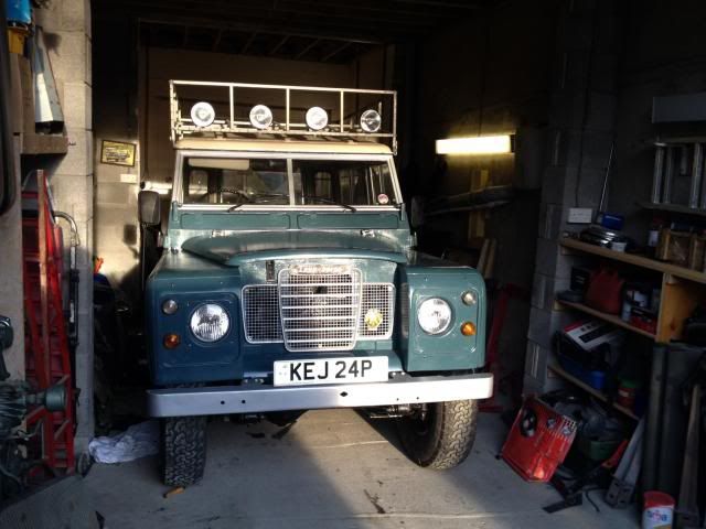
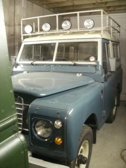
Right bit of an update, some of you ymay have seen her on the cover of classic land rover a couple of months back


I've also fitted the spare to the bonnet and dug out my old hubcaps which are a bit of a marmite issue with some people!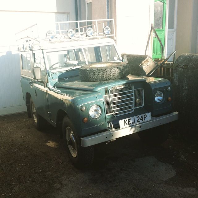
-
If the oil capacity is the same as a Fairey one it should be approximately 0.4 litres (3/4 of a pint)
-
Looks a lot like a Fairey one except it hasnt got a dipstick
-
Right, I'll get round to finishing off the gearbox bit eventually, takes more time than you think to write it up. But anyway, some pictures for those who get bored at looking at bits of gearbox, I took her out for a spin today to the breakwater and my brother took these photos


-
Right back to business,
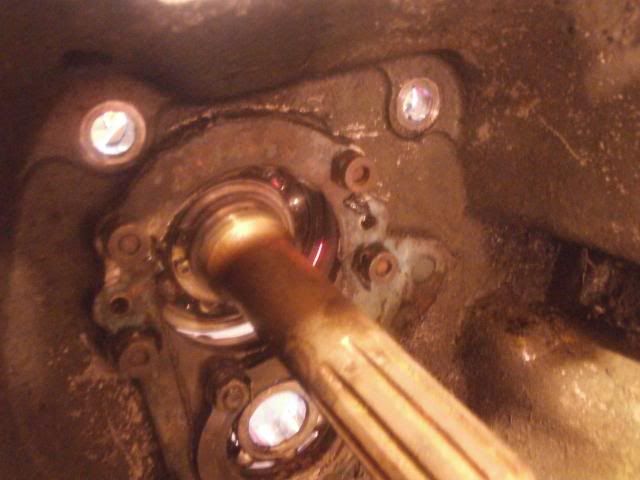
First thing I did was to overhaul the bellhousing.
The input shaft was drifted out of the bellhousing (backwards) leaving this: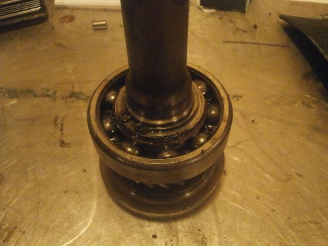
Using circlip pliers, the circlip was removed. This will be replaced. Note: there is a thrust washer under the circlip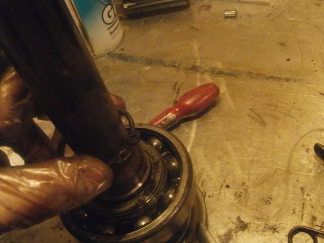
Holding the input shaft (gently) in the vice, the bearing could be heated up with the blow torch until it fell down the shaft after a slight tap with the mallet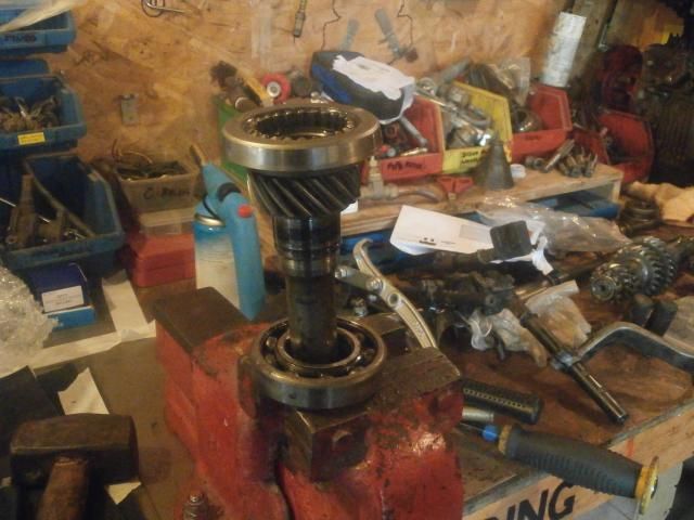
The new bearing was heated up with a blow torch until it could be dropped into place on the shaft and the thrust washer was replaced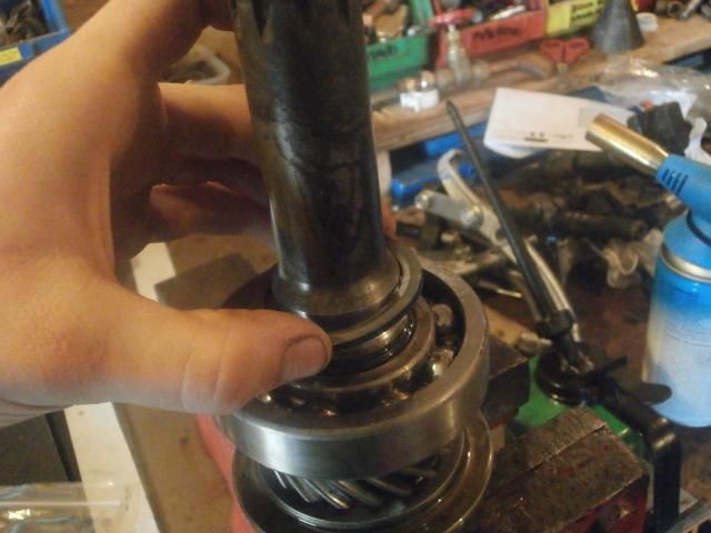
Circlip being fitted using circlip pliers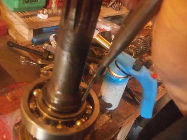
The assembled input shaft. The seal land looks good so no worries there of any pitting ragging the new oil seal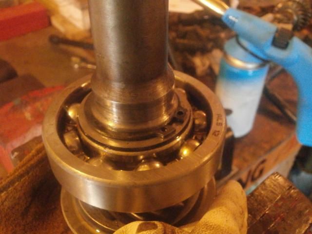
The bellhousing casing was rested on top of the vice so there was enough room underneath for the input shaft to drop down. The casing was then heated up until the bearing could be dropped into place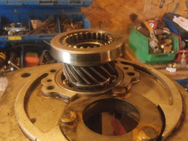
The layshaft bearing could then be dropped into place using the same technique (heating the casing up) an the bearing carriers can be put in place (The input shaft bearing carriers are handed)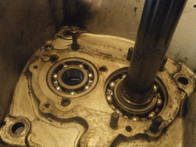
Layshaft bearing cover plate thing goes down with the lip going against the bearing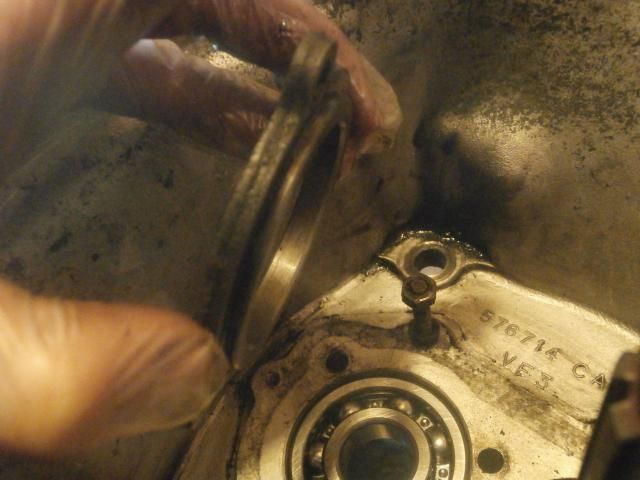
Nuts and lockwasher in place with the tabs being lifted up. You might find putting a prybar through the clutch fork hole and tapping that is easier for lifting the tabs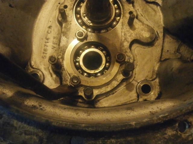
The bellhousing was then wrapped in rags to keep everything clean and put aside till laterNow then, rear mainshaft bearing housing overhaul.
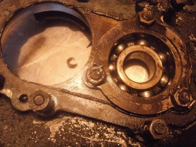
I started by removing the old oil seal, removing the large circlip which retains the bearing and then drifting out the old bearing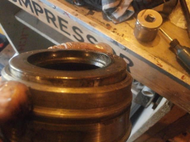
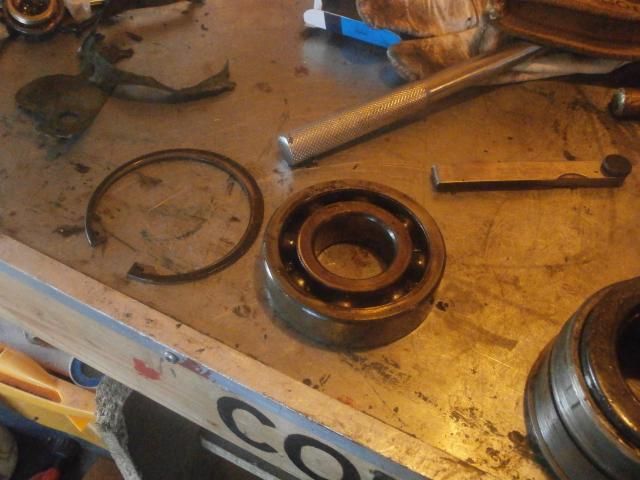
The manual says to put loctite on the outer race before fitting to hold into the housing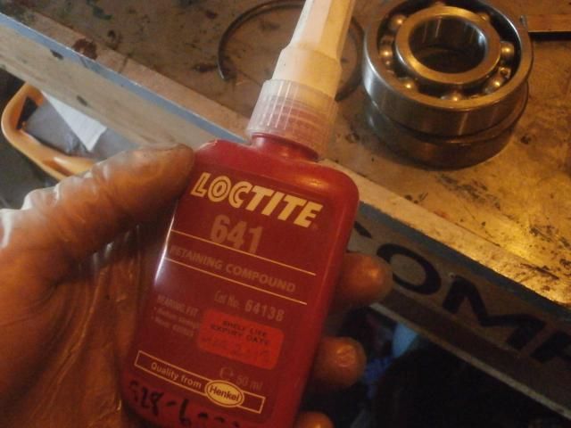
New bearing being pressed into the housing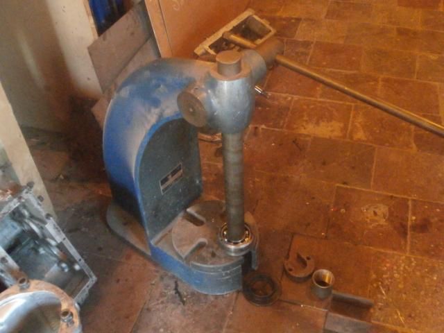
Once the bearing was pressed in and the circlip refitted, I fitted the oil seal (a corteco one)
Here you can see the layshaft outer race in position (more on this later), this was done at this point for convenience.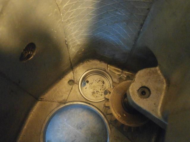
Again loctite was used but on the housing itself this time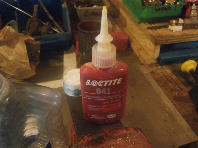
Drifting the housing into place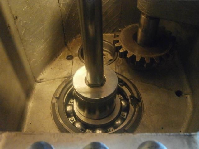
The circlip which holds the housing in place can be refitted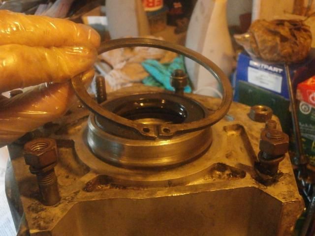
-
Got the on the roll stuff from paddocks. To fit you can either:
a) Find a strip of aluminium to put inside and rivet into place like the original
or b) do what I did and glue them on with sikaflex (it is expensive stuff though unless you can get it like I did from work
-
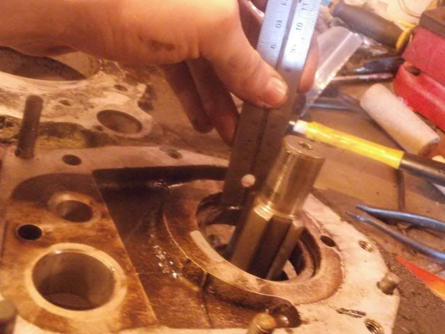
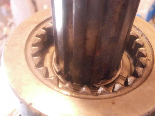
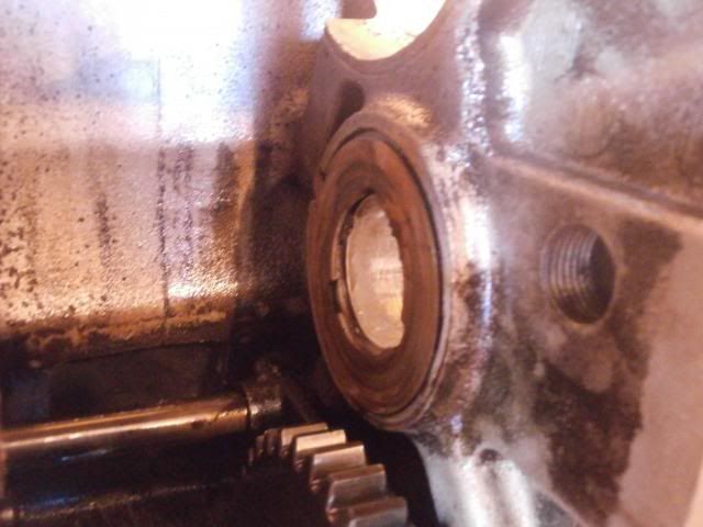
Right update time, stripping the transfer box!Before removing the shaft, I checked how far into the casing the bearing sits (6mm) as a reference for when I refit the bearing
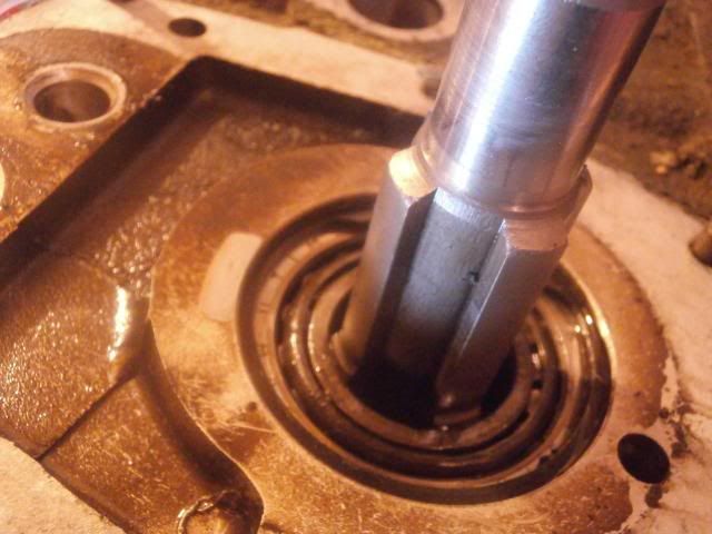 The shaft is first drifted rearwards with a mallet
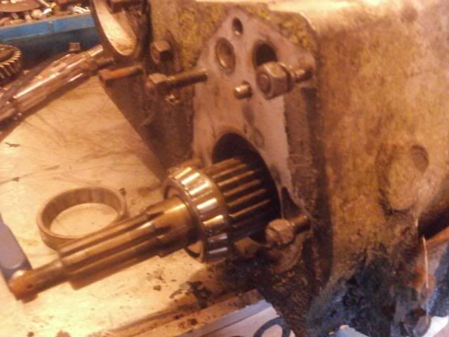 The large circlip is then removed
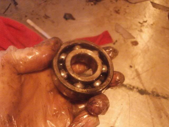
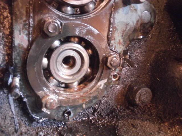
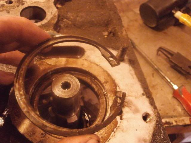 Next I drifted the bearing inner race off the shaft (apologies for the blurry action shot)
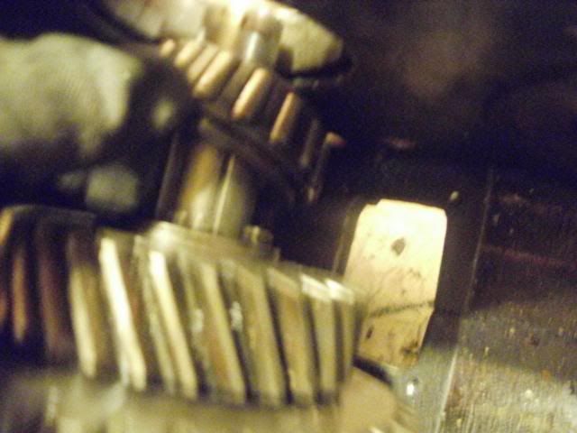 Then the circlip holding the thrust washer and the gears in place was removed allowing the shaft to removed
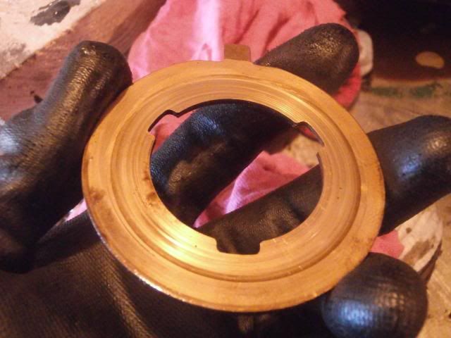
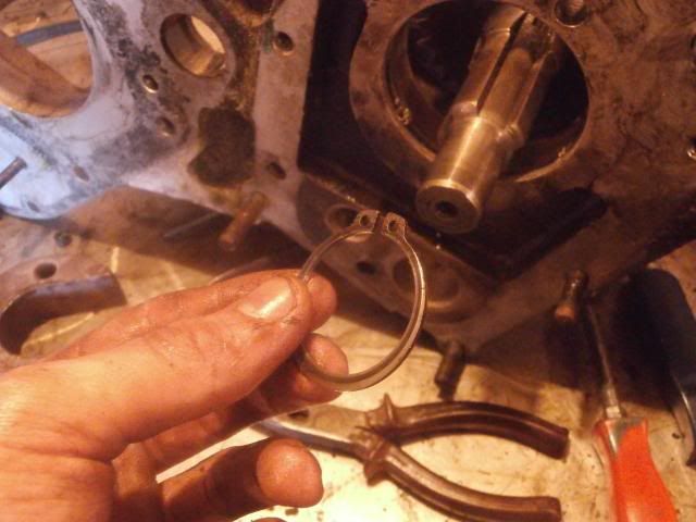 The thrust washer
 With the shaft out I could then drift out the other bearing race
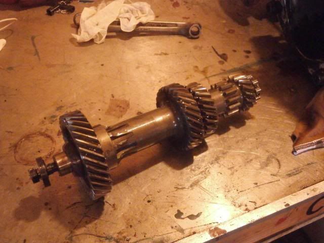
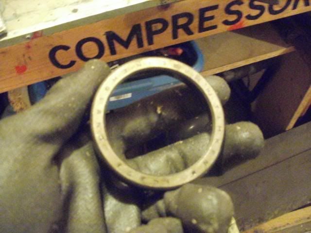 (This next bit is from my other thread showing the various bits of the shaft) as I forgot to take photos this time"The order the bits are on the shaft
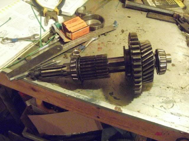
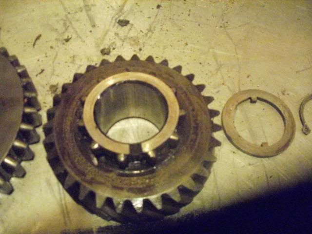
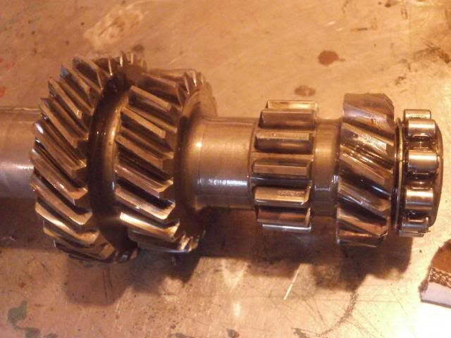
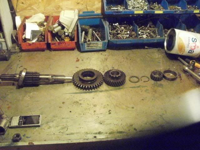 Bearing outer race, inner race, circlip holding gears on and thrust washer
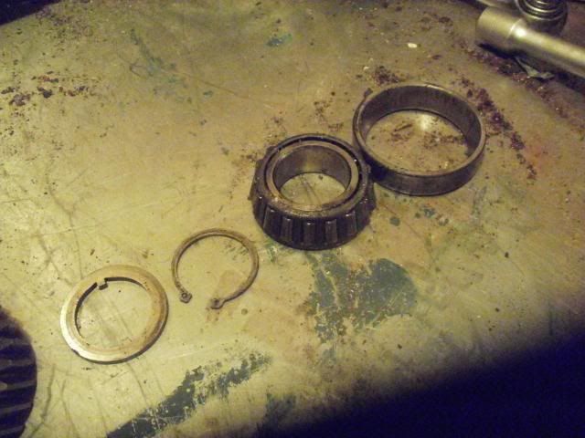 High gear
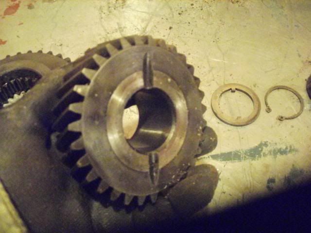
 Low gear
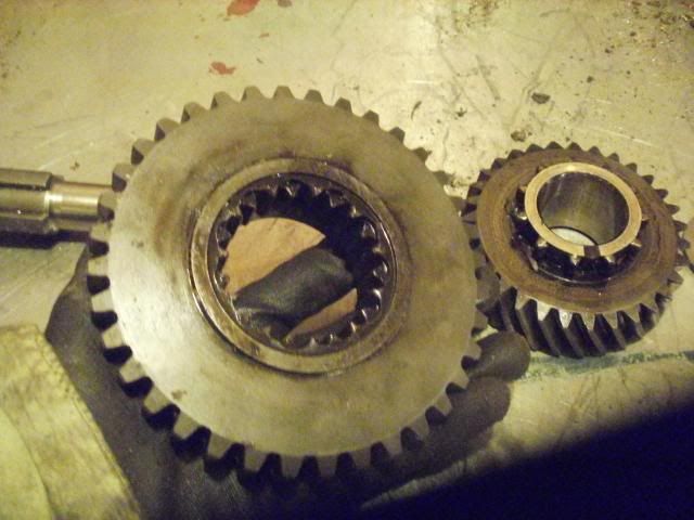
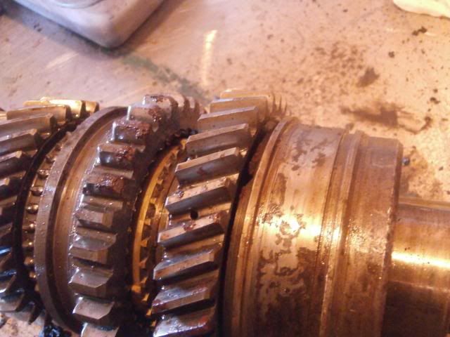
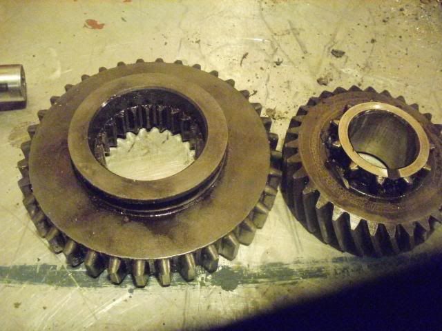 Shaft with bearing
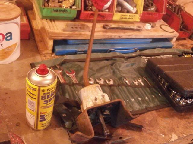
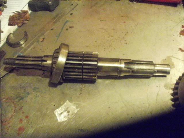 "Today I sorted out the workshop to get ready for rebuild
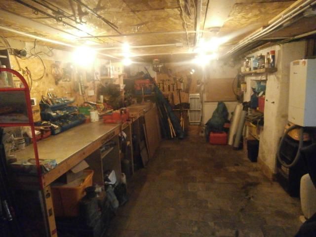 and immediately set about making a mess sorting out the parts I have
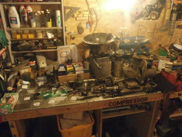
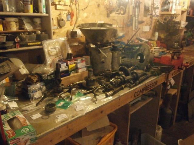 Rebuild starts tomorrow
-
Ask on the facebook forums, probably get a better response there
-
Thank you
Thats very helpful -
I would just look at the nut off my old box which is still in the series but its got the overdrive on it at the minute so i cant easily check the measurements without a lot of faffing around. Ta for the part numbers, I use paddocks for a lot of stuff rather than craddocks (unless they have something paddocks dont) always found them too be cheaper and customer service is good too
-
I applaud the desire to set the nut with the correct torque, but am puzzled by your request.
You have got the nut, which gives you the dimensions, simply cut the tool from whatever you have to hand, be it an old socket or a scrap end of tube. When I made mine I didn't have a gearbox in pieces, so I bought a nut to ensure the tool fitted.
HTH
No I havent got the nut, its missing off the gearbox I'm doing
If I had it, then yes I'd do the sensible thing and measure it with my calliper -
What are the dimensions please? I.D, O.D and tooth size if its not too much trouble
Am rebuilding a gearbox at the minute and think I might as well make up the tool to torque it rather than use a punch and a hammer
-
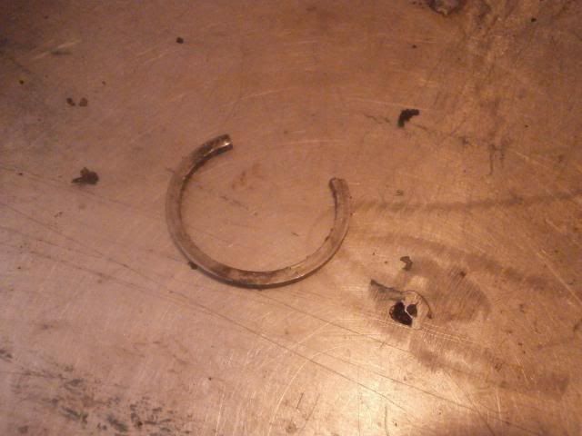
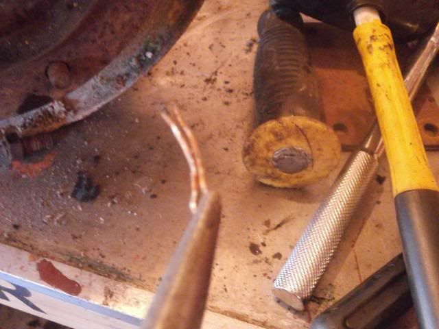
Right then, disassembling the mainshaftI strted at the front end and worked back, starting with third gear. The first job to do is to remove the snap ring (basically a circlip but without the helpful little holes to get a pair of pliers in). With help from my Dad I removed the clip with 3 thin screwdrivers, its a bit awkward but doable
 You can then withdraw the thrust washer and the third gear
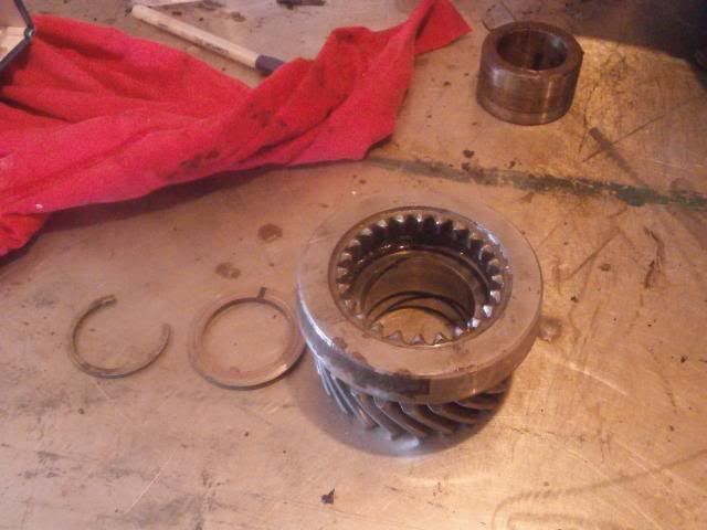 Then withdraw the distance sleeve and bush
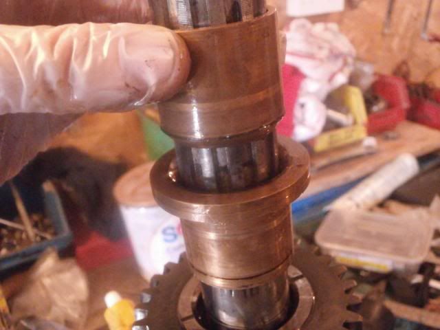 Then you can withdraw second gear and the thrust washer as well as the front synchro cone
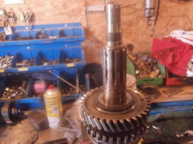 Next I removed the rear mainshaft bearing/ oil seal housing. I had to use a set of pullers for this as I didnt want to damage anything.
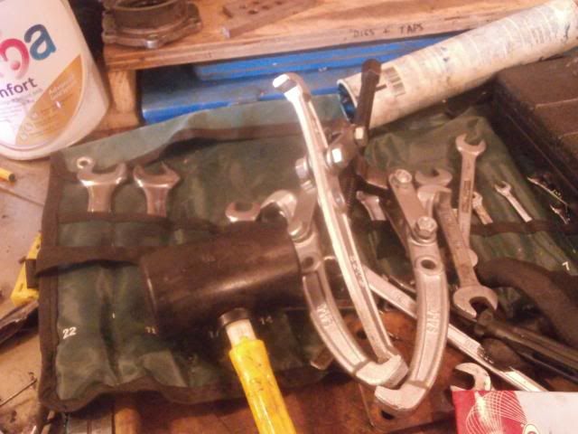

 To dismantle the rear part of the mainshaft remove the thrust washer
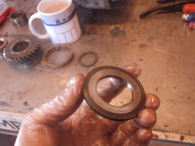 It has 2 grooves on the forward face (facing the front of the gearbox)
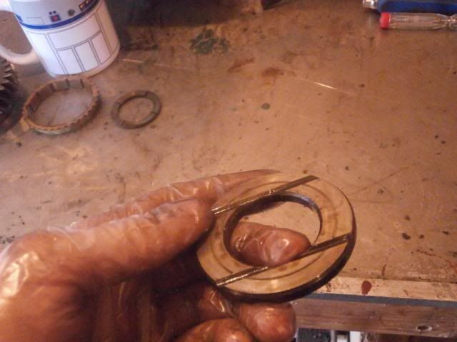 First gear can now be removed
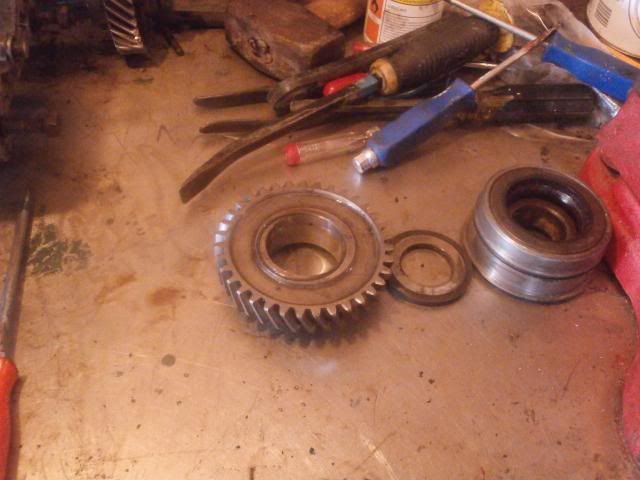 As can the first gear bush
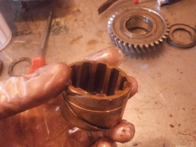 The rear synchro cone is removed
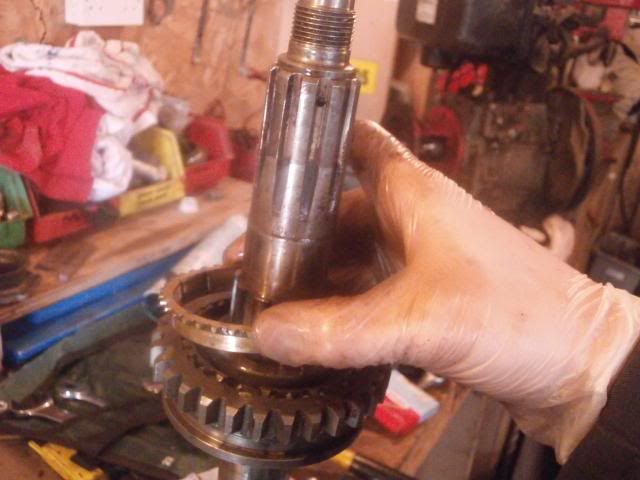 As is the first-second synchro hub which looks decent according to my granddad (hes done quite a few of these in the past), it certainly operates freely enough but I think I'll swap the detent springs and things whilst I'm at it and give a good dose of looking at
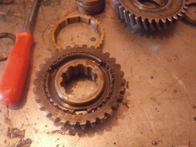 The components split into front of mainshaft and rear, all cable tied together to keep them in order
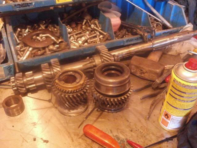 Next attention turned to the bellhousing again. I slackened off the nuts for the bearing carriers at the back of the bellhousing before knocking the bearing through, again using a suitable socket as a drift
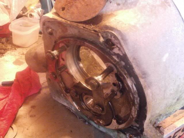
 For the layshaft bearing carrier, the tab washer first needs the tabs knocking flat
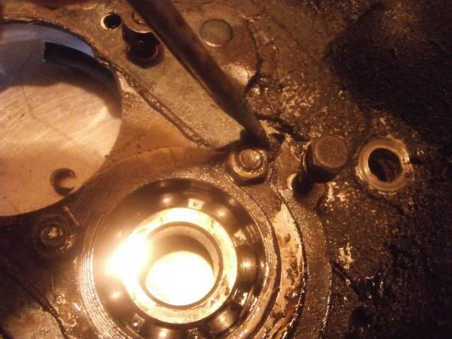
 The nuts can then be undone using a 1/2" socket
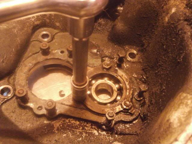 The lifted off lock washer
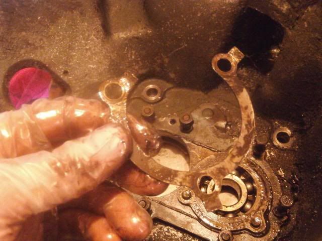 The rear washer holding the studs can also be removed
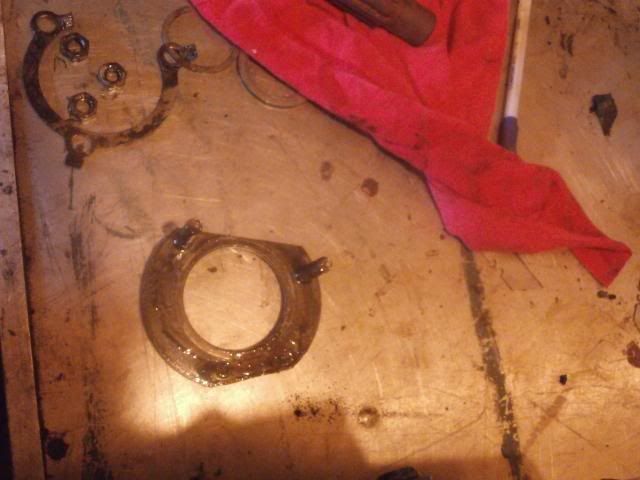 and the bearing knocked out
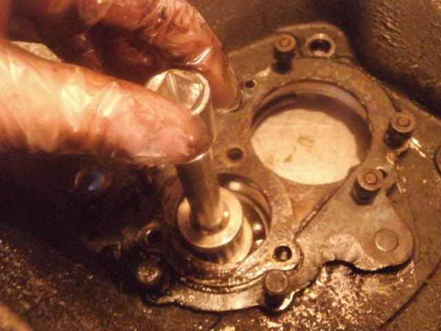
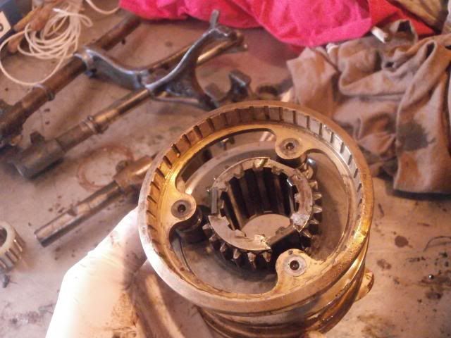
 Thats it for the mainshaft, attention then turned towards stripping the transfer boxFirst task with this is to remove the speedo housing by removing the 6 nuts and spring washers using a 5/16" whitworth spanner again
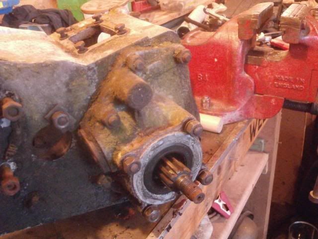 Some of the studs came out with the nuts, as you can see one is longer than the rest to go through the thickest part of the housing
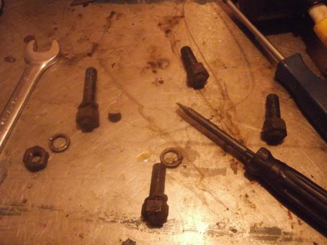 The housing can now be pulled off
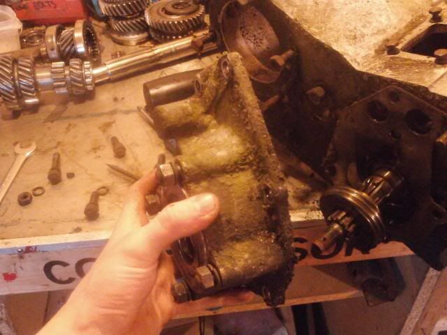
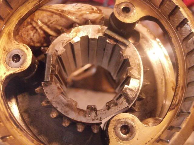
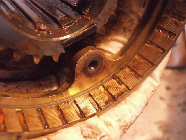
 Between the housing and the transfer case are some shims. On my spare transfer box, there were 3 but on this one there are 4
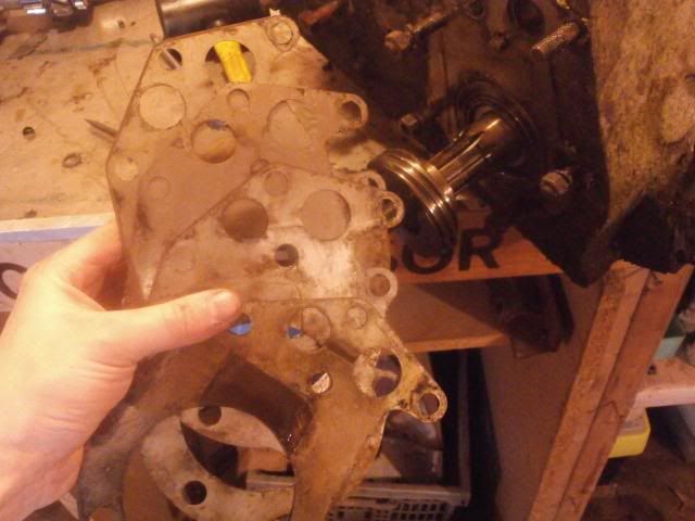 The worm gear. This isnt fixed to the shaft but interestingly it runs off friction
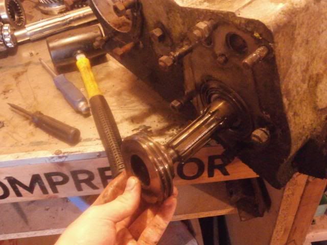 Shall carry on with stripping it down tomorrowSo far the list of bits to change are:Gaskets,Seals,Bearings,Detent springs and balls,Thrust washers,1st gear,2nd gear,3rd gear,Layshaft,Bushes,3rd/4th synchro hub (on closer inspection the teeth were worn)Gear lever will get swapped off my old box as will the handbrake back plate and drum
-
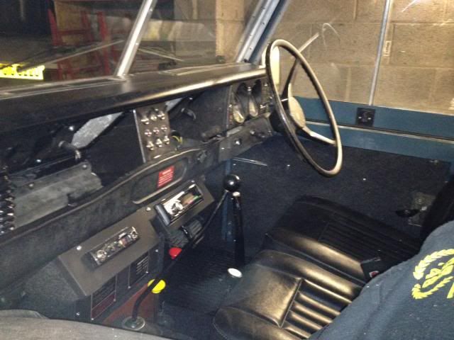
Very good but a few points.
1, you make no mention of the steel coregated washers under the injector nozzles that are supposed to act as heat sinks and stop carbon forming between the nozzle sides and the bore in the head.
2, The 2.5 thermostat shown is the wrong one for the thermo housing top you have, you want a std series thermo or a spacer making to fill the counterbore in the top casting as a 2.5 thermo housing top is flat.
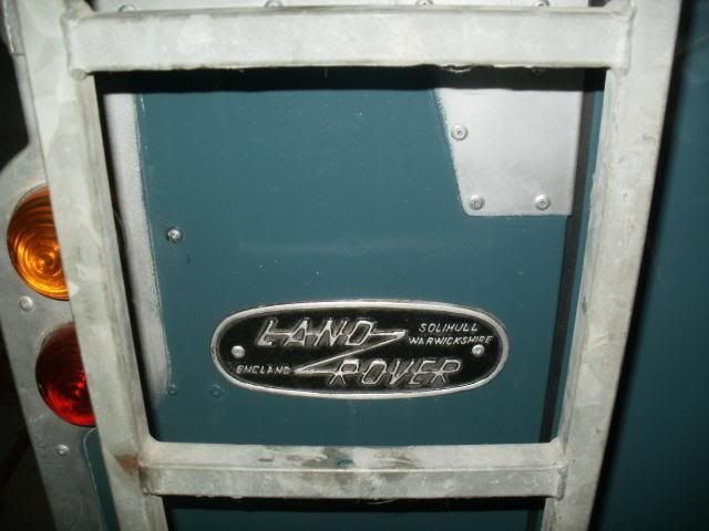
3, The spare wheel carrier shown on the back door if used for a spare wheel as its shown in the pics will rip the middle out of the door as it has no crossbar in the frame at the top of the mounting plate, the crossbar is another piece of door frame section.
4, The selector shaft seals in the gearbox you have stripped are the later style 'o' ring with spacer which IMHO work better than the usually supplied original pattern square seals that now don't even grip the shaft when new. So stick with the late type.
1. I didnt mention them because I didnt swap them , I didnt realise they were there,seeing no mention of them in the manual for the 2.5 diesel, , only the copper and steel washers where it seats.
2. The thermostat works perfectly well in this set up, when running it reads bang in the middle of the temperature range. Is always been on the engine I believe, certainly my granddad never swapped it when he had it, only the actual thermostat. Anyway, it is a 2.5ltr engine which is why it has a 2.5 thermostat top on it?
3. That was fitted by my granddad a good few years ago and I never realised that that would be a problem due to the size of the spreader plate it has fitted (this is a bought example from somewhere, will have to ask him so cheers for that. I might have to swap it for a swingaway I think as the wheel on the back is a 6.50 and I run 7.50s. A 7.50 at the back will completely obscure the door lock. Other option is to move it across I suppose, I shall see. Something needs sorting with it anyway
4. Thanks for that, I've ordered some of those o-rings now
-
 1
1
-
-
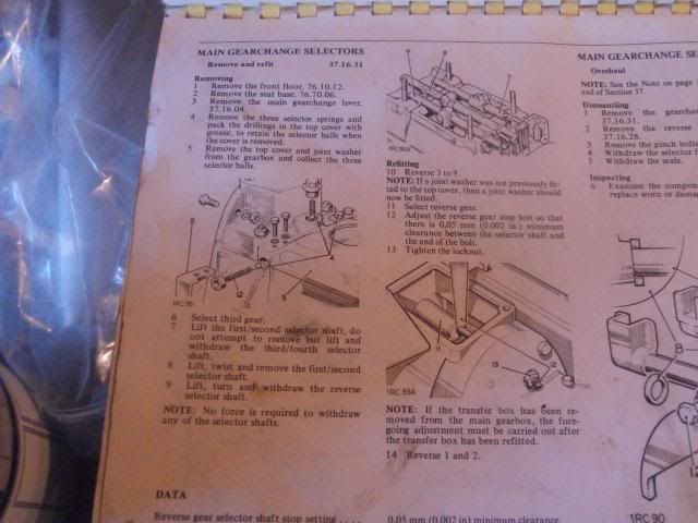
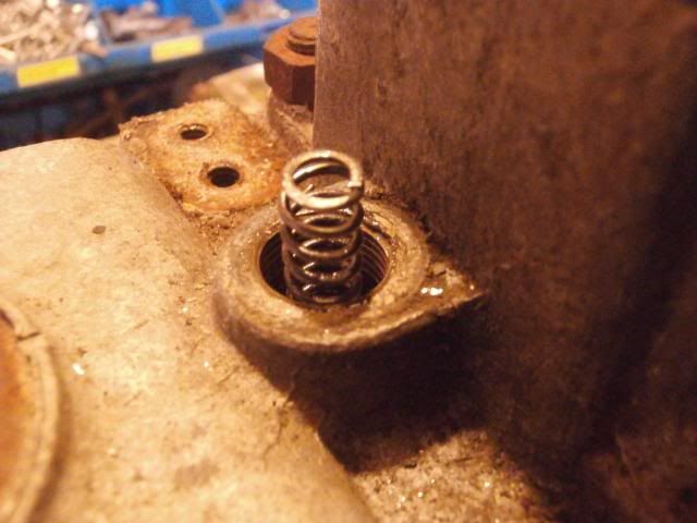
Right then, onto the selectors.
 First I removed the reverse and 1st gear detent springs using an 11mm spanner
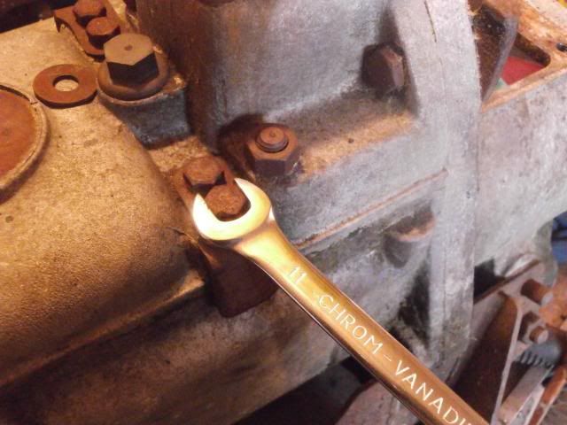
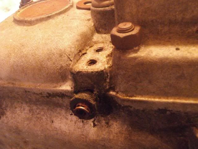 There is a seal between the spring and the bracket
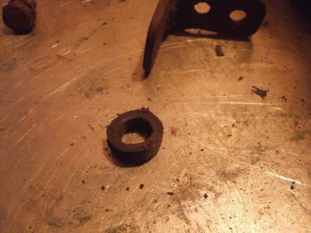 Next was the top detent spring for 3rd gear, which cmae off using a 5/16" Whitworth spanner
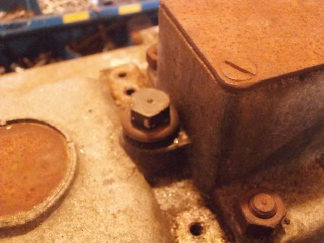
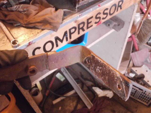
 Before removing the top cover, I had to remove the overdrive bracket which had been fitted to this gearbox. The nuts and bolts came off with a 1/4" whitworth spanner and socket
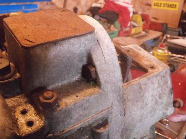
 The 2 nuts also need to come off using a 5/16" whitworth socket/ spanner
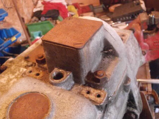 The stud came with the nut
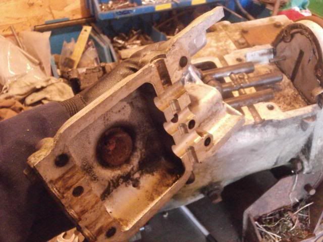
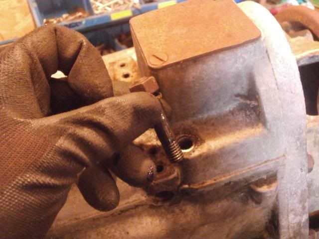 The cover can then be lifted off revealing the selector shafts. Be careful not to lose the 3 ball bearings that were under the detent springs
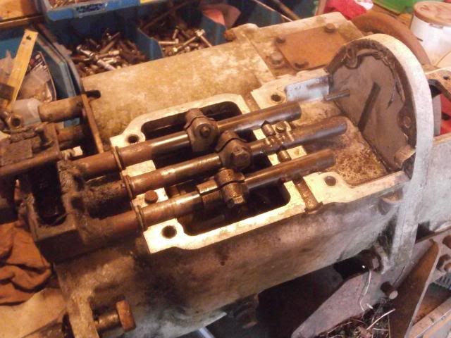
 The detent spring assembly
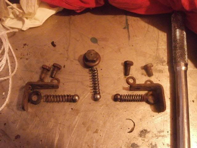 There are 2 small rollers on top of the main casing, be careful not to lose these
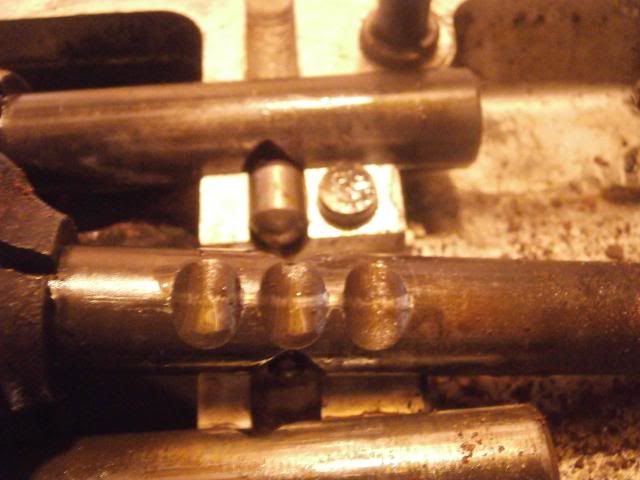 Select third gear and the selector shafts can then be lifted out. Its a bit fiddly to do this with the shafts in place but they do come out. First out is the reverse shaft
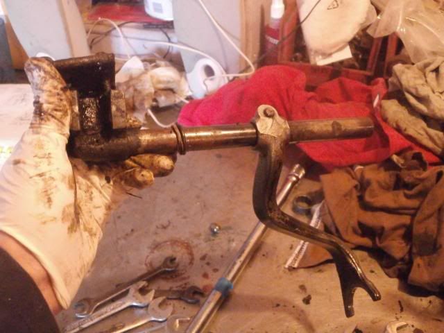 Then the 3rd/4th shaft
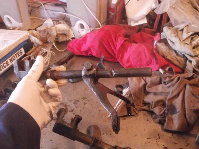 This has a small pin along the shaft, be careful it doesnt drop out or you'll never find it again
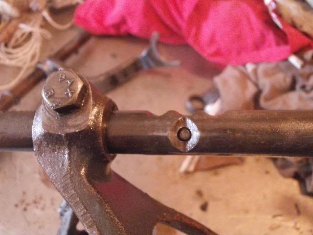 First selector
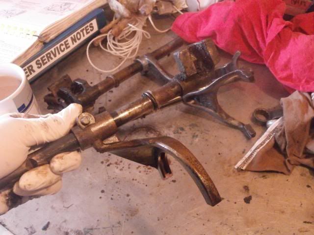 Revealing the mainshaft
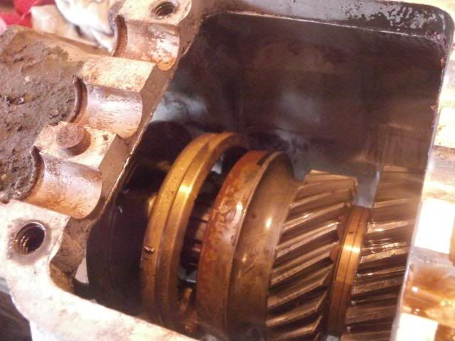 The bearing slides off the mainshaft
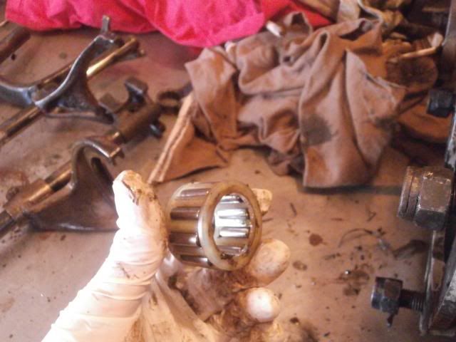 As does the 3rd/ 4th synchro hub
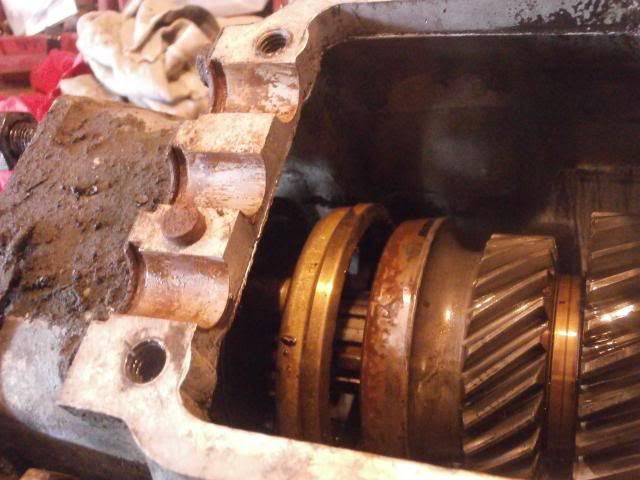
 Mine doesnt look bad at all aoart from its missing a leaf spring (which I found in the bottom of the box)
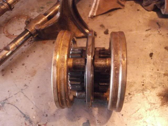
 Before drifting the mainshaft out, I decided to take the transfer box out to make everything a more manageable size
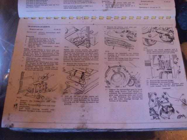 Before starting this the brake back plate needs removing. Take out the split pin in the castle nut and undo the nut (I had to use an impact gun on this as it was tight and due to lack of rear mainshaft gear I cant put in gear)
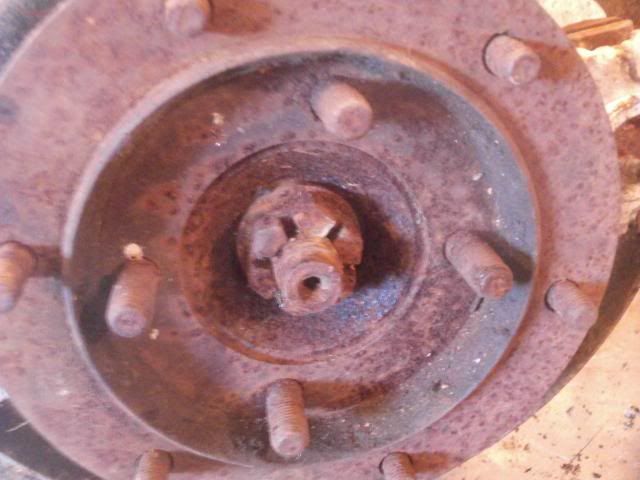
 The rear output flange then just slides off
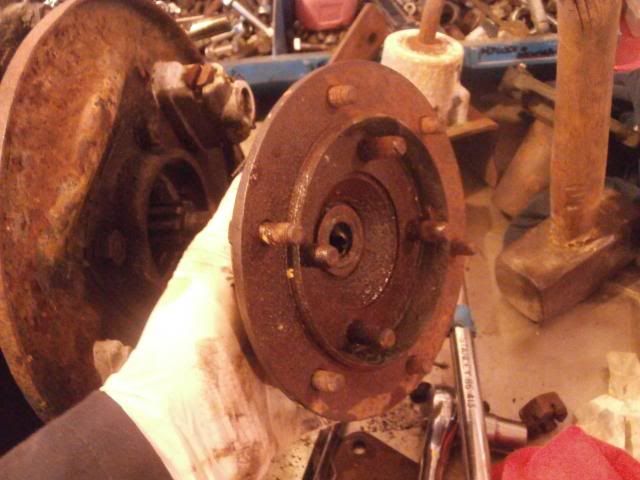
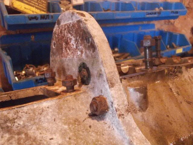
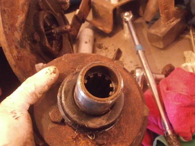 These 4 nuts holding the back plate to the speedo housing are next to be removed, again with a 5/16" whitworth spanner
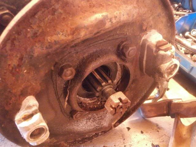 Once thats off, take off the retaining nut and bracket for the intermediate shaft, again 5/16" whitworth
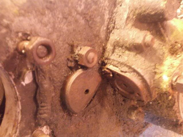 Using a pry bar, you can withdraw the shaft
 Before taking it out fully, take off the bottom plate (check theres no oil in it first though, I forgot so ended up with a workbench covered in old EP90
 )
) The shaft can now be withdrawn whilst you support the intermediate gear cluster
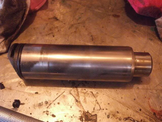 The cluster can now be rolled out the box
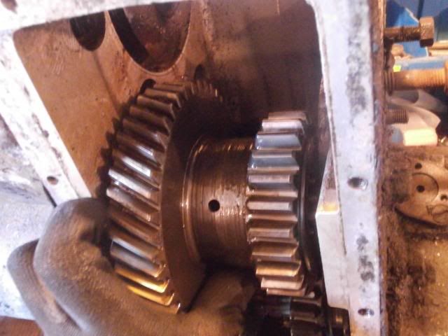 Revealing the thrust washers either side
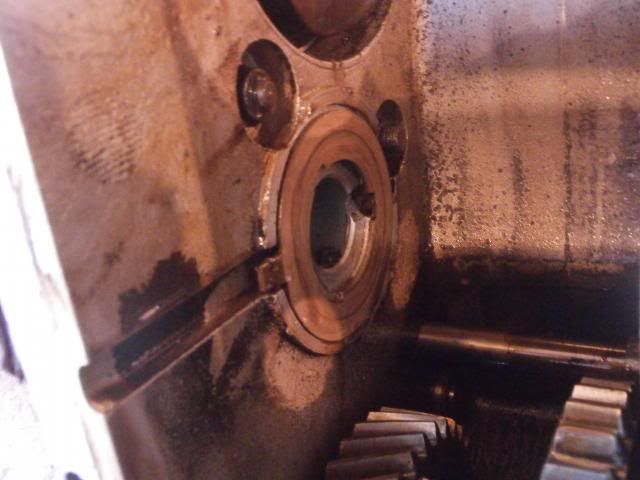
 They're a bit worn so will get new ones
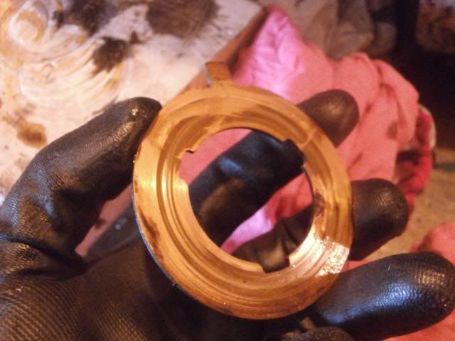
 Gears look good
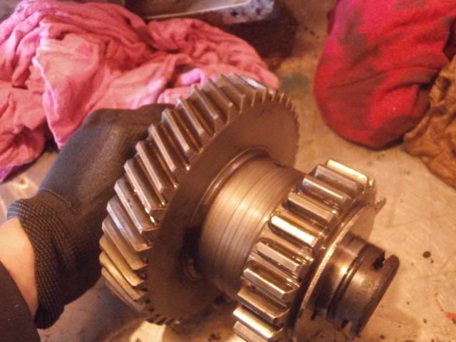 With that out of the way, the fastenings holding the gearbox to the transfer box can be removed (using you guessed it, a 5/16" whitworth socket)
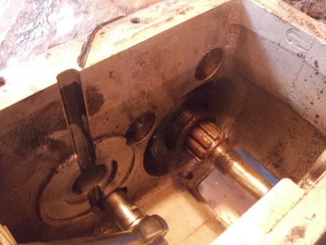 Next the external fastenings were removed
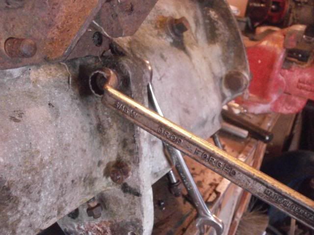
 Allowing the boxes to be split
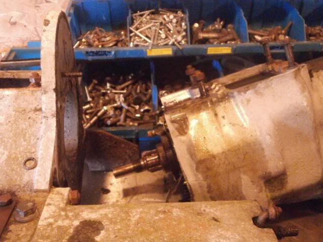 With the transfer box out of the way, it was now time to remove the mainshaft.First task is to remove the mahoosive circlip holding the housing in place
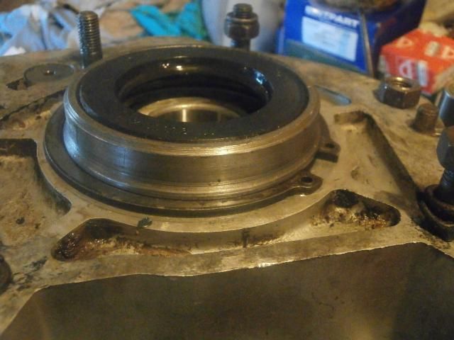
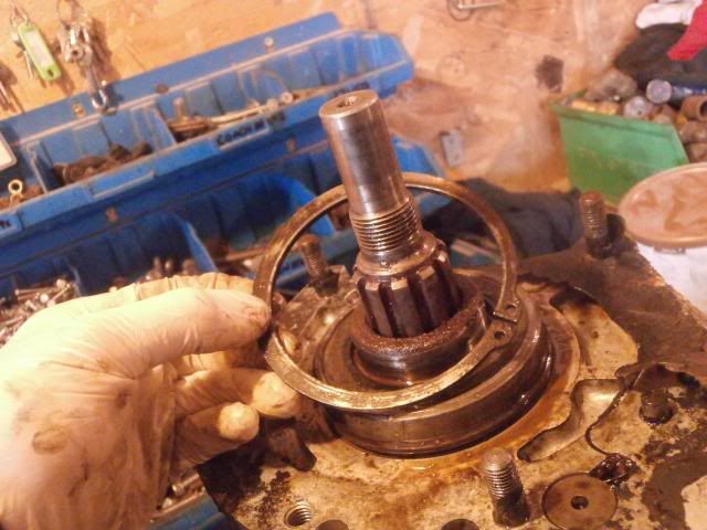 Then the mainshaft can be drifted downwards and out of the box (support the casing on bits of wood to give the shaft more room to come out the box)
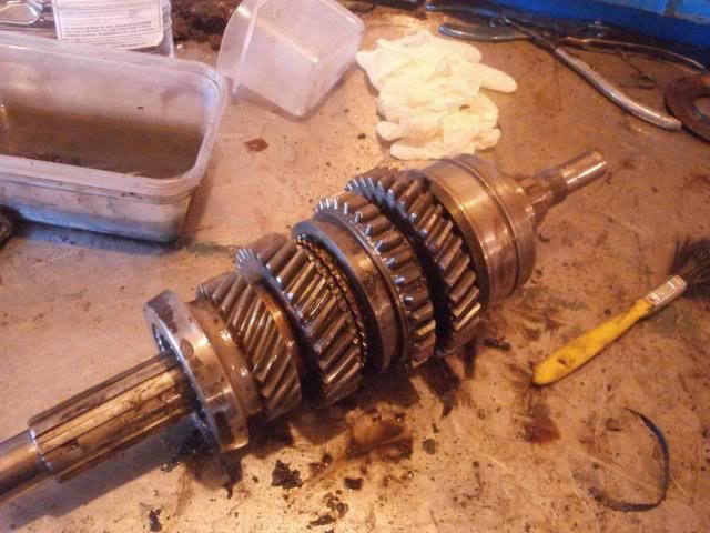 Little bit of surface rust on one or 2 components but not bad
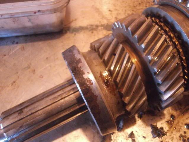
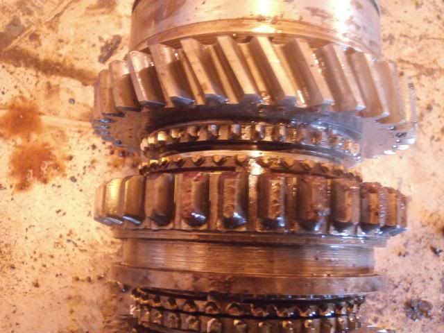 No chips on the teeth at all which is somethingNext up is splitting the transfer box and front output shaft housingFirst remove the cover plate using a 1/2" spanner
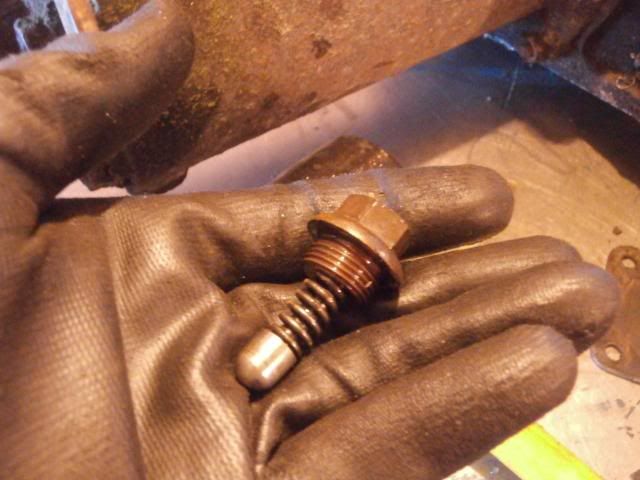
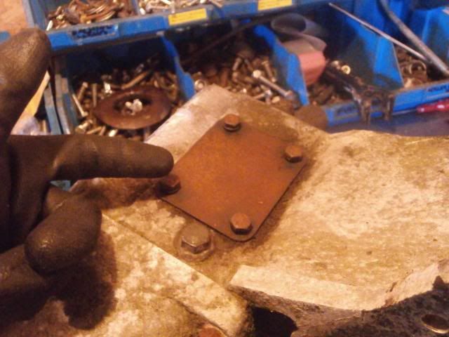 Then remove the Detent spring using a 5/16" whitworth
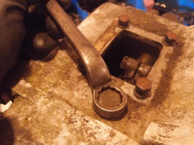
 Remove the transfer selector fork pinch bolt using a 1/4" whitworth spanner
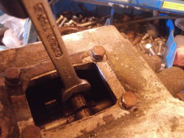
 Next remove the fixings holding the housing to the transfer main case
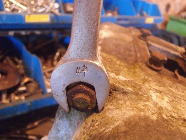
 Once the output housing is free, remove the 4 wheel drive selector
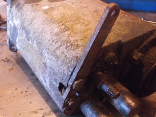
 The dust cover can now be removed using a 3/16" whitworth spanner
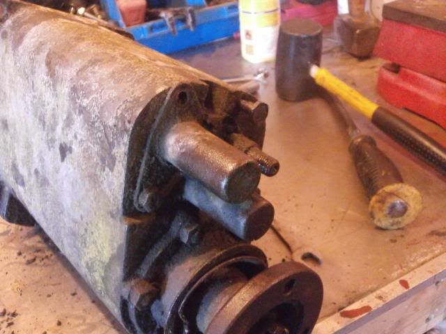
 The shafts can then be drifted out gently
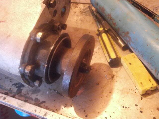
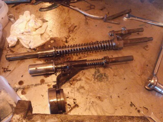 Next remove the front output flange, which is exactly the same process as the rear one
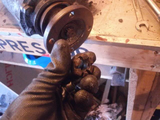
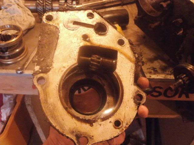
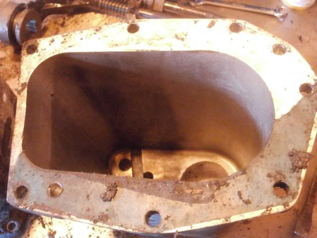
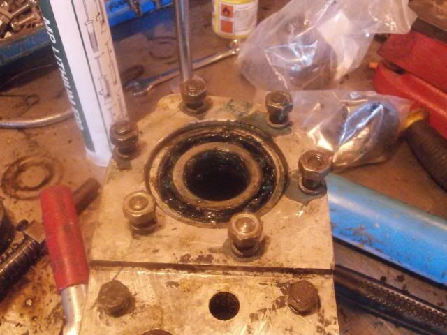
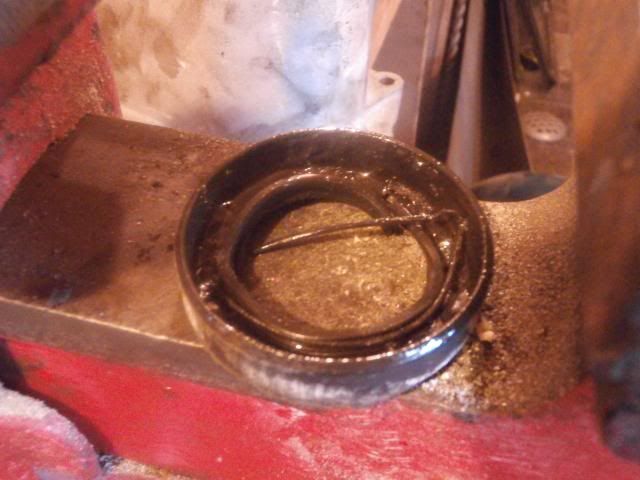
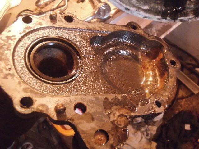
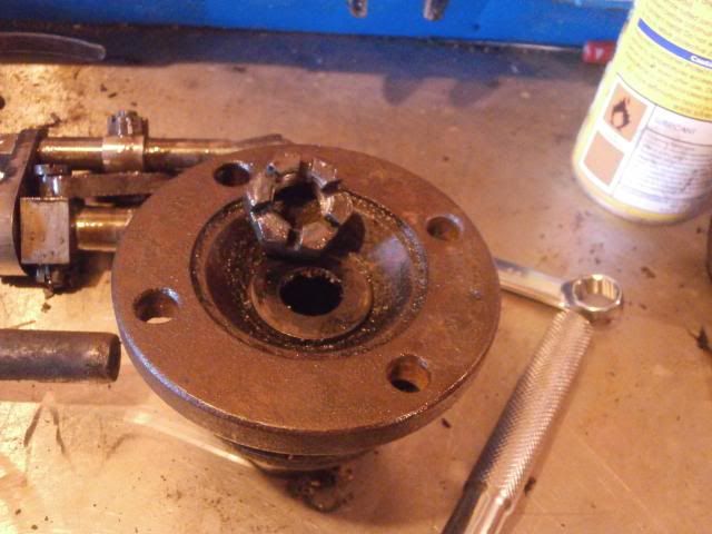 Revealing the oil seal housing
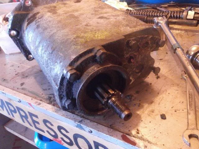 Which can be pulled off once the nuts are removed
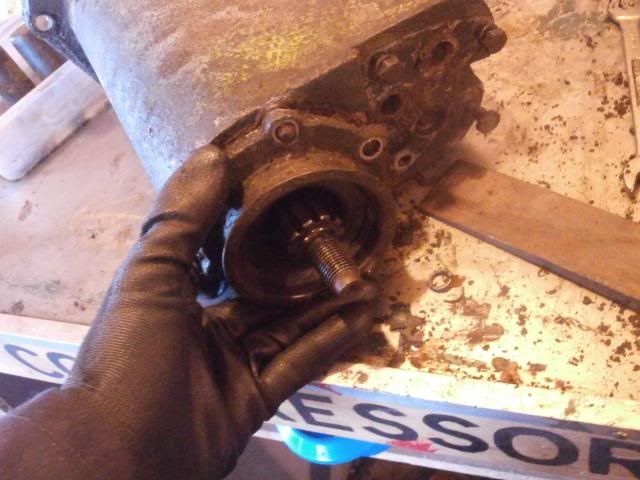 The output shaft can now be withdrawn
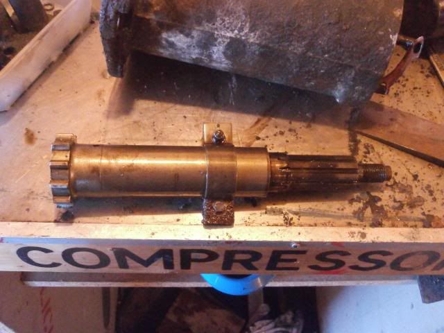 The bearing can now be drifted out. I used a 32mm socket on the end of a long extension bar as a drift for getting it out
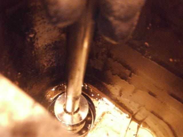
 Now, as I have another spare output housing which was clean I decided to use that one
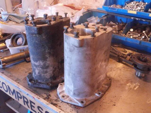
 I decided to rebuild the output housing as I have all the bits required to do itThe bearing was greased and pressed in the housing using the trusty old fly press
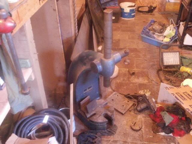
 A gasket was then made for the oil seal housing (using the old one as a pattern)
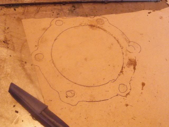 The old oil seal was then prised out (put the housing pointing down in the vice, flanges resting on the jaws and punched the seal out)
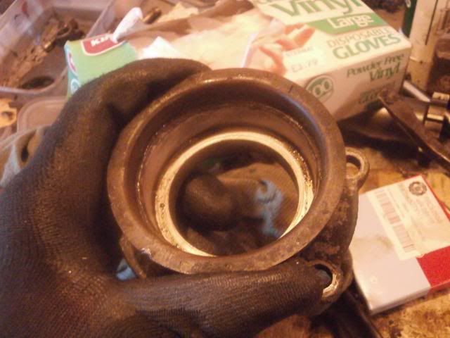
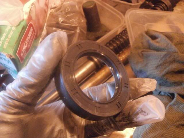
 The new seal
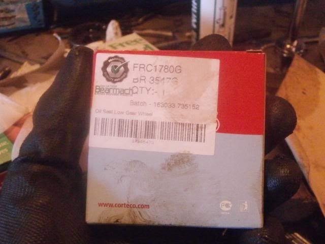
 Smear the outside of the seal with hylomar blue
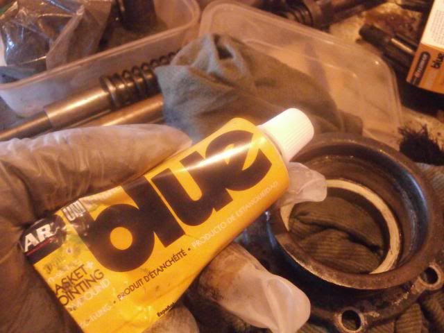
 Press the seal in place, I like to put a smear of grease on the lip to lubricate whatever gets pushed through it.
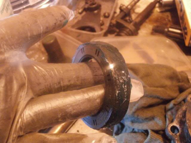
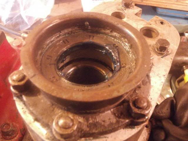 The housing can then be bolted back on with the gasket and a smear of hylomar either sideThe front output shaft can be then put in place again. The flange can then be slid on, this is a spare one I have, the mud shield on the other one was a bit mis-shapen
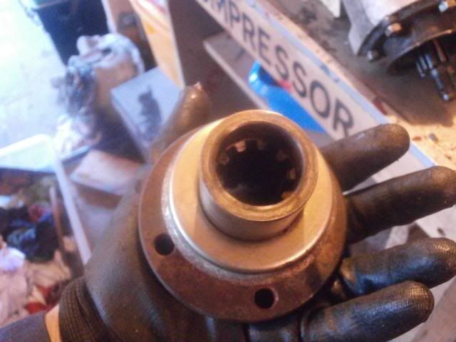
 Washer in place
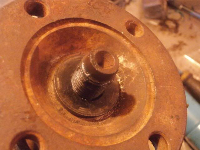 The nut is then put in place and torqued up to 85 lb/ ftTomorrows job is selector shafts and strip down the transfer box I think
-
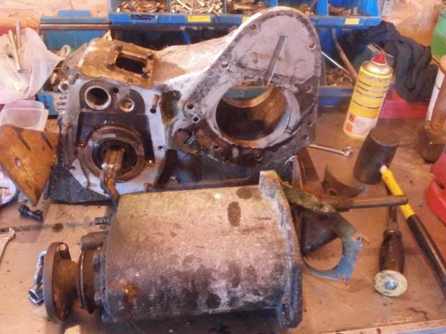
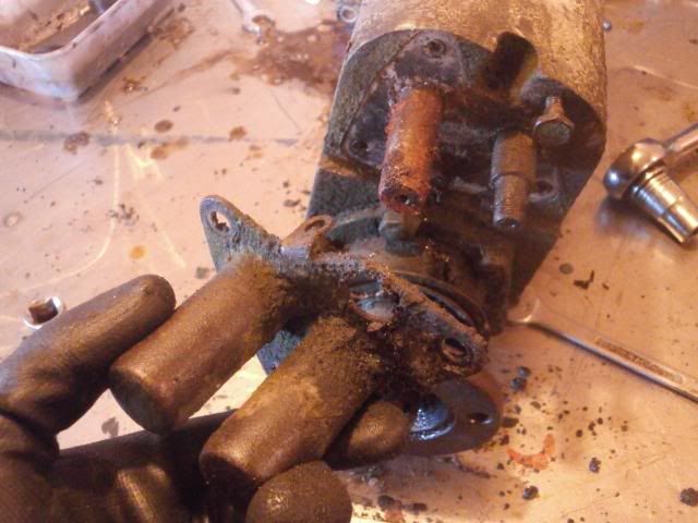
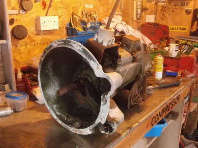
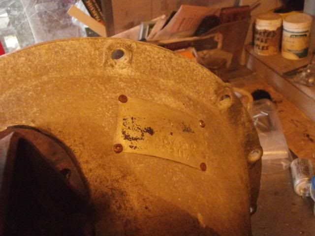
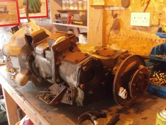
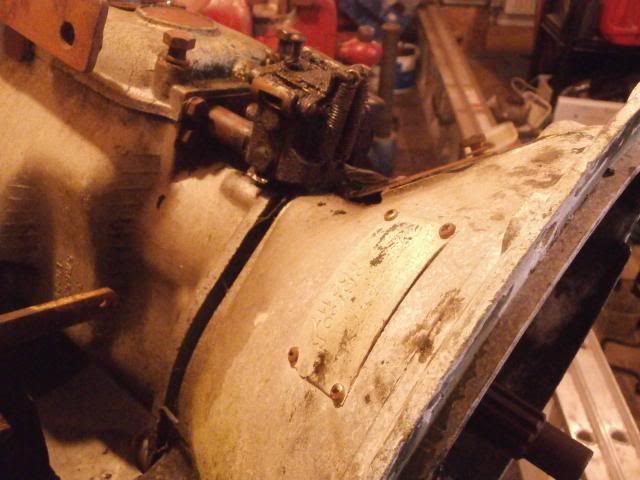
Right then, today I picked up my new (second hand) gearbox out from Selwyn at Bryn Glas Garage in Bryngwran who I highly recommend for Land Rover related things.Picked it up out of the corner of the yard under some brambles and theres a plate on the bellhousing which shows it to be a factory recon unit (hard to make it out but it reads " The Rover Co. Ltd, Factory Rebuild" )
 This is the only serial number I've found on it, on the side of the main case, "5766588A", does this make it a suffix A box?
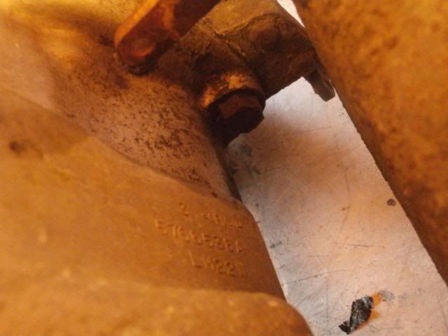
 First task is to remove the gearlever.
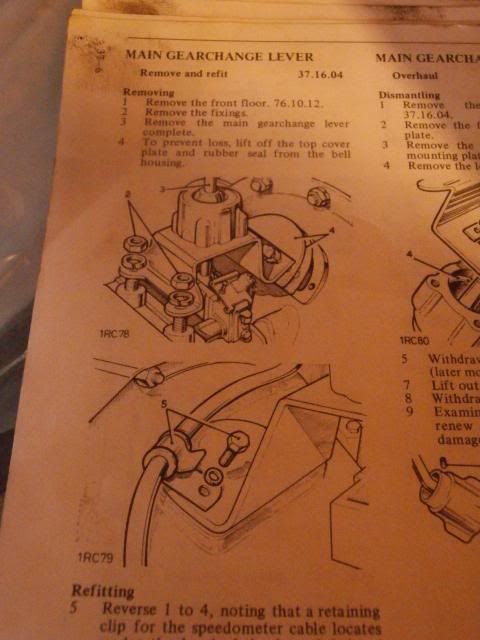 This I did by first removing the 2 larger bolts at the rear using a 15mm spanner (the gearbox I know should be whitworth but found a 15mm spanner to fit perfectly)
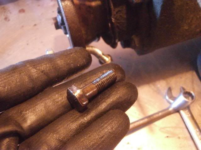
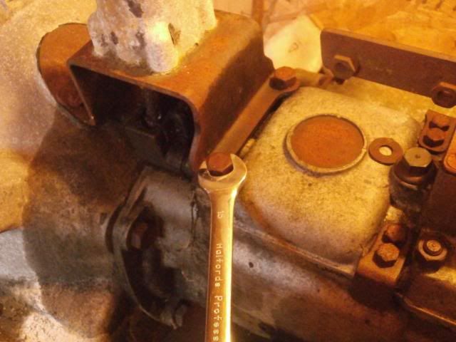 I then removed the shorter bolt at the front using an 11mm spanner. (there should be 2 bolts but only one was present)
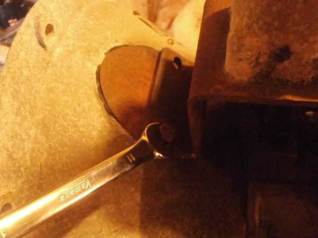 The bolts holding the main gear lever in place
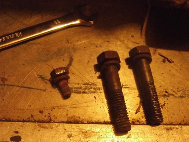 The 2 smaller bolts also hold down this plate in the bellhousing
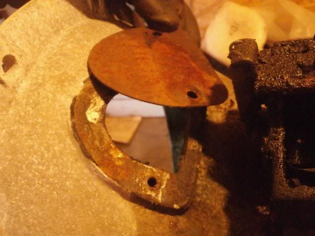 As soon as it is removed, I like to put the bolts back where they came from to avoid losing them and so I dont get confused as to what goes where
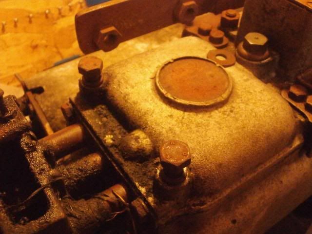 The whole gear lever assembly can be pulled off
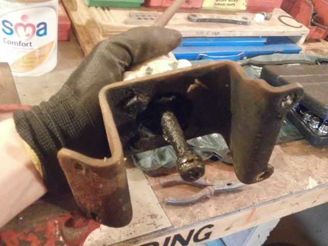 The selectors
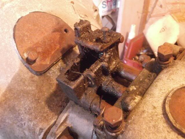
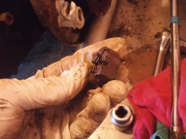
 Next job is to remove the Bell housing, before this can be done however, the clutch fork needs to be removed. The book gives it like this
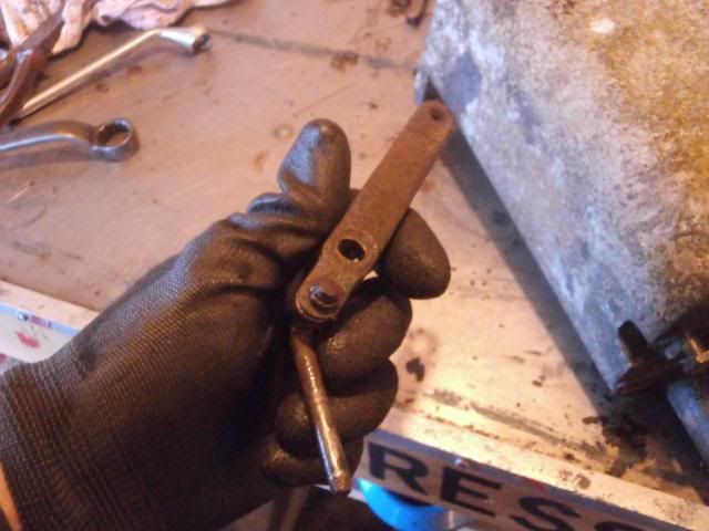
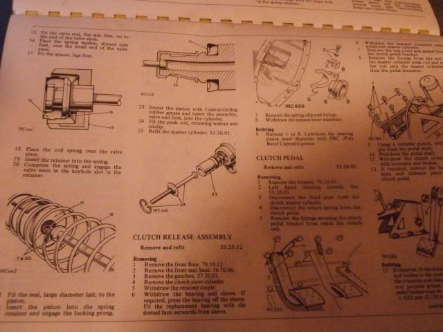 The bearing was not present on mine and the fork simply popped off the ball joint (I think the clip is worn)The ball joint
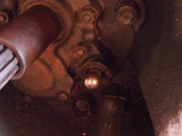 The fork
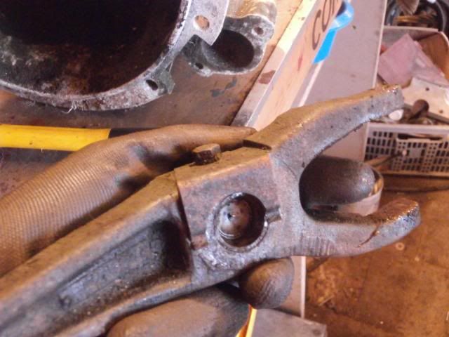 Next up is removal of the bell housing itself
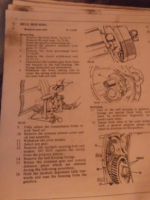 First is to remove the oil seal housing in the bell housing
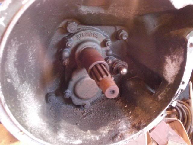 The 4 upper nuts where removed using a 1/4" Whitworth socket
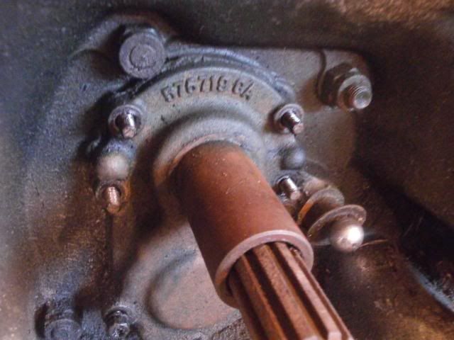 The 2 lower bolts and 1 nut were removed using a 7/16" socket
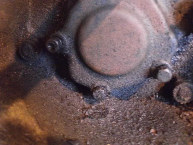 I had to knock the assembly with a mallet to get it free enough to pull off
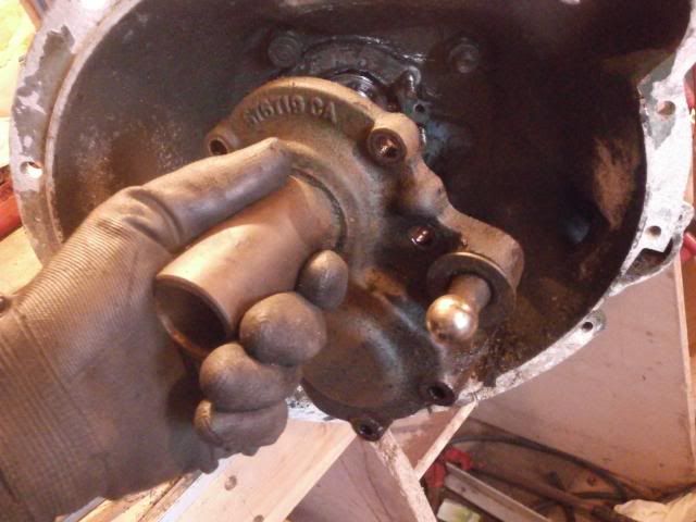
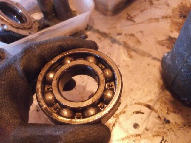
 There is some play in the upper bearing so that will be replaced
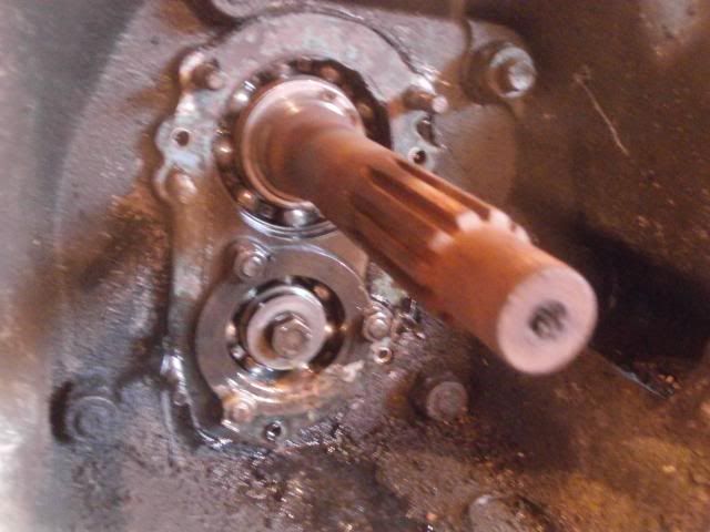 The layshaft retaining bolt is next to be removed
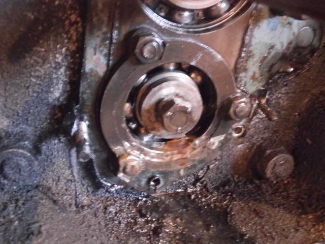 I used a socket on this and by holding the mainshaft by hand I was able to undo the bolt (it wasn't particularly tight)
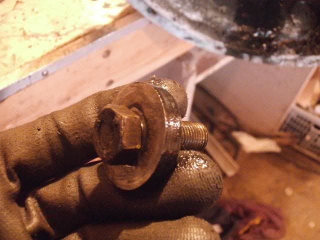
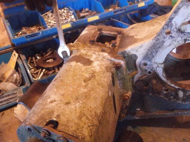
 The 4 fixings which connect the bell housing to the main gearbox casing are next to be removed. I used a 7/8" spanner and socket on a breaker bar to get these out. (as you can see the earlier oil seal housing bolts have been put back in place so I don't lose them)
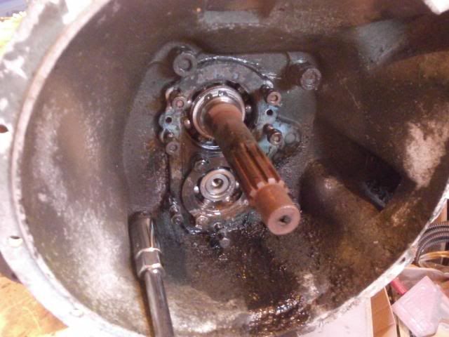 The bellhousing was then tapped with a mallet and it started coming apart
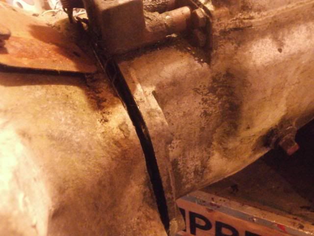
 When the bellhousing comes off it brings the layshaft constant gear and conical distance piece with it
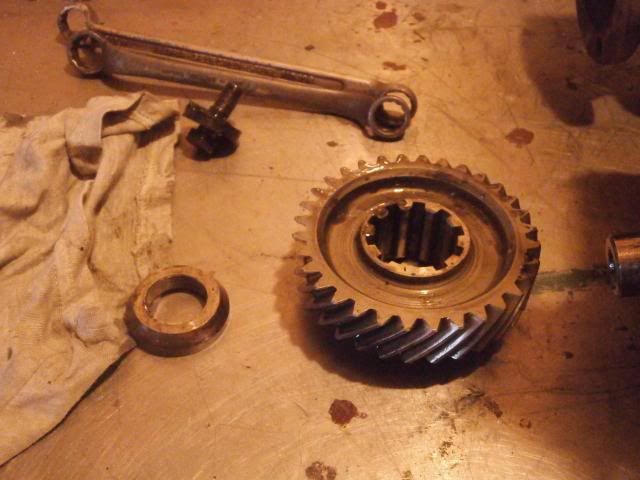 This is how they should look on the layshaft
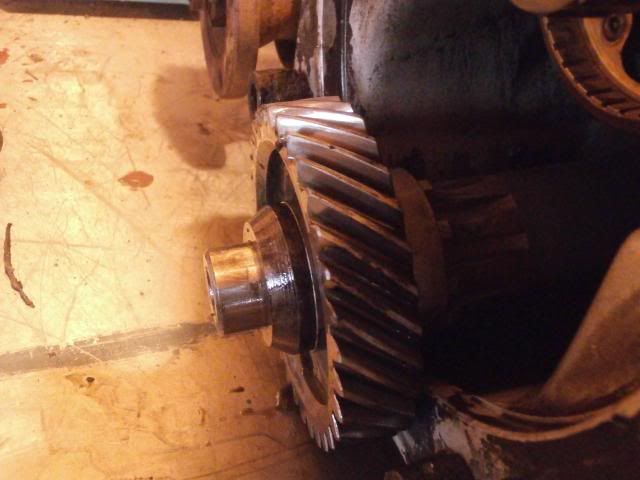 Bellhousing
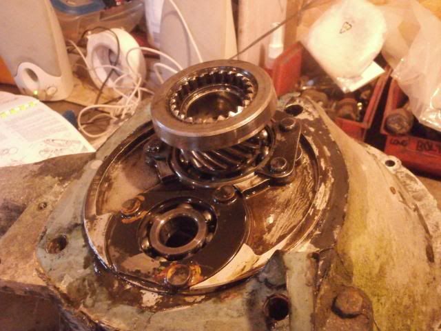 The layshaft was then pulled out
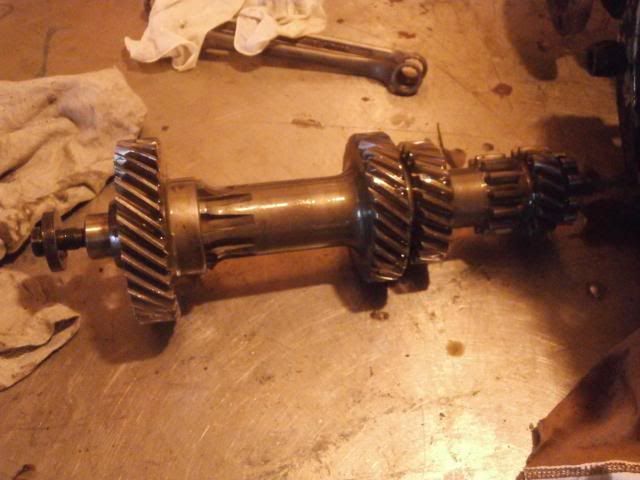
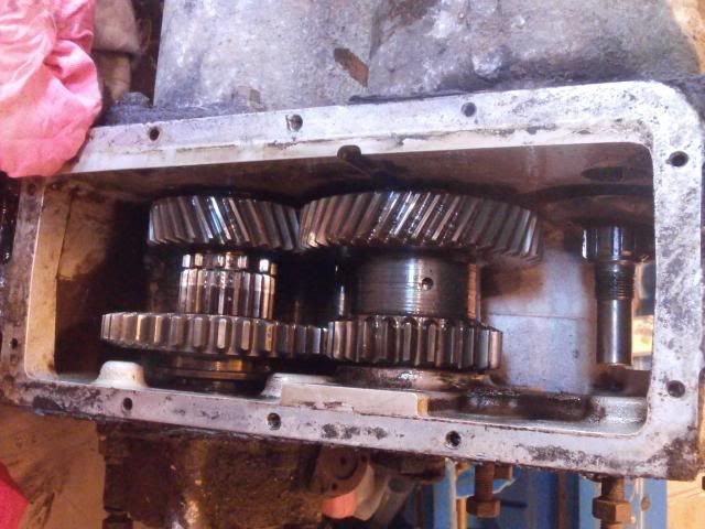
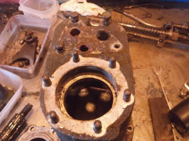
 A view inside the main casing
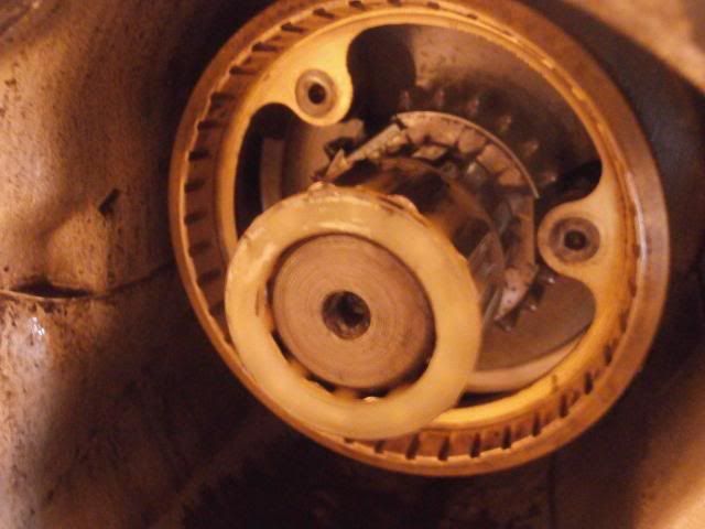 Reverse gear
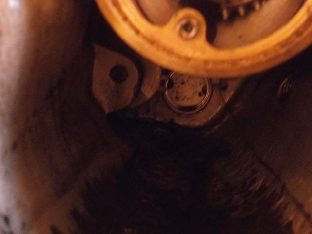 Tomorrows job is to look at the selectors and fetch the mainshaft out to have a look at it
-
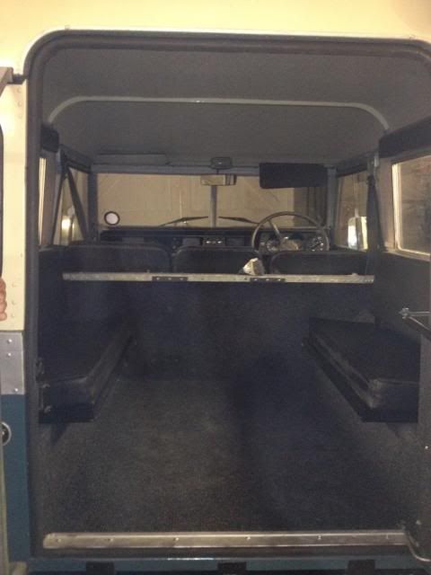
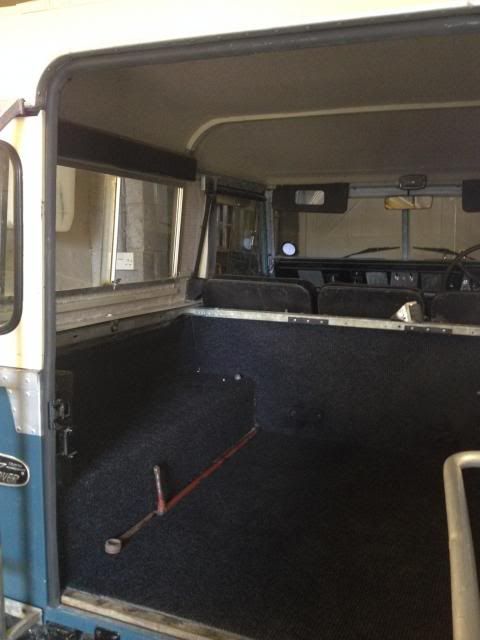
Right then, a little bit of a delayed update by a couple of weeks.2 weeks ago I fitted my headling (read as some mighty fine cream carpet from carpet right) stuck in place using thixofix contact adhesive. Makes a massive difference to the noise level
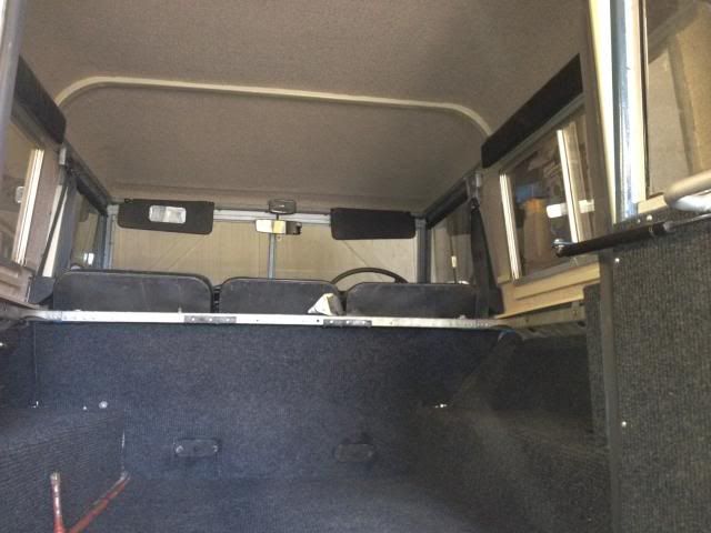
 Then it was the turn of the Anglesey Vintage Rally where I was exhibiting the landy (identifiable as being the only exhibit brandishing an L plate
 )Heres a couple of pics of it by the camping arrangements (all carried by series)
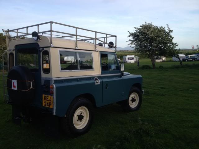

 It develop a problem on the way there though of having the synchromesh go resulting in me losing 2nd gear
 Just revved up in first and stuck it straight into third gear, went perfectly well other than that cheers,Sam
-
I had to grind off a god awful hoop that was welded on my bumper, it still bears the scars of that monstrosity to this day as well as a few dents. My landy may look pretty straight in my thread but its far from perfect and i wont change it for anything, end of the day its an honest 40 year old landy, doesnt pretend to be anything else
-
Few more
-
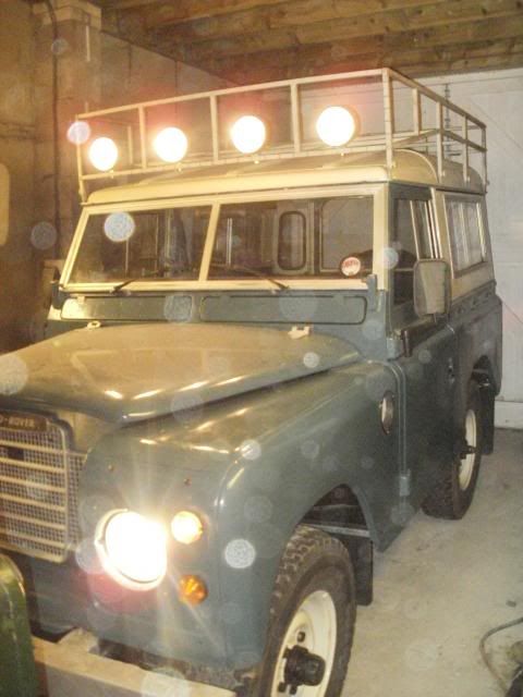
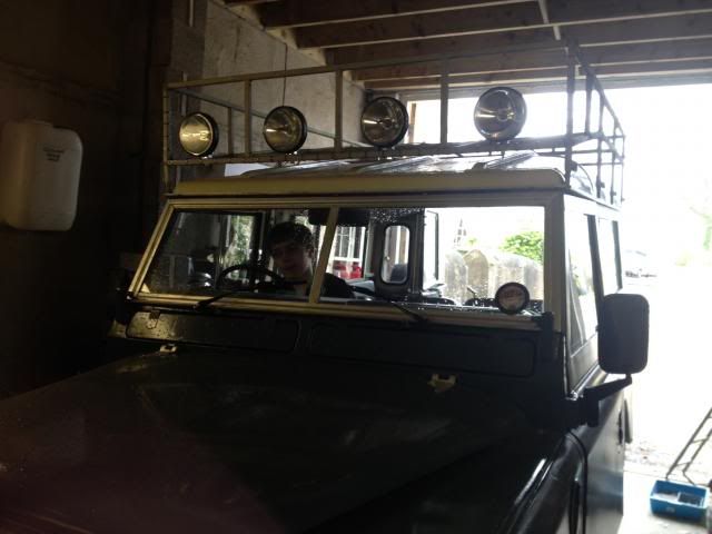
Got my roof rack and spots fittedSpotlights and worklights:
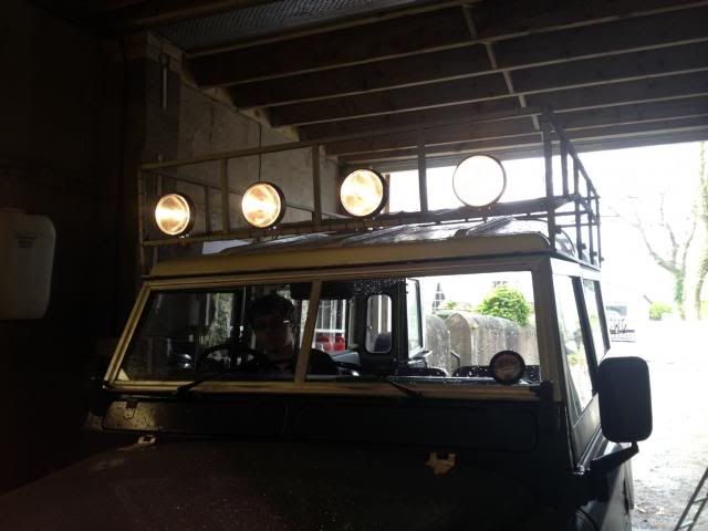 Worklights :
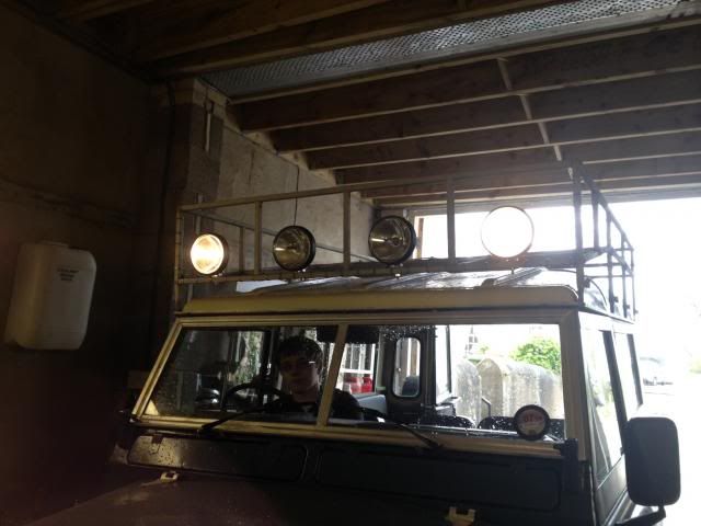 Spotlights:
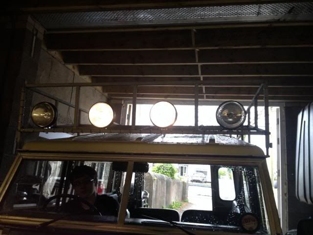
-
Fit the turbo back on. I've never understood why people take the damn things off!
Jon
Horrific insurance costs for any owners who are still quite young. Partly why I kept the 2.5 N/A in mine when I rebuilt it
-
Went out in it earlier for a spin up the A55
-
Few more
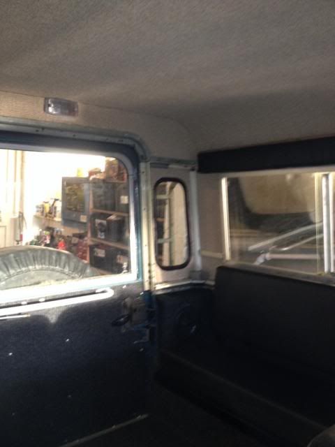
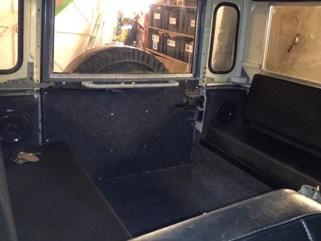 Got the front door cards made up and fitted
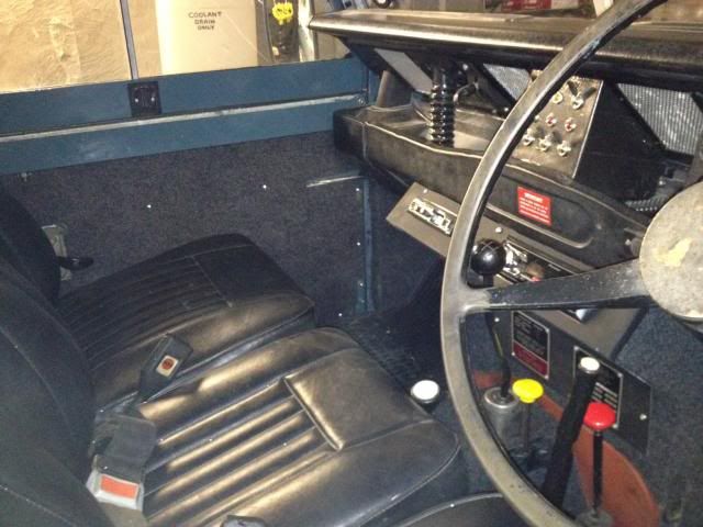


 )
)


Uneven slow running. 2.5 D
in Defender Forum (1983 - 2016)
Posted
Mine started surging momentarily on idle when i took the throttle offto change gear. turned out to be a frctured injector pipe causing air to get in. Of course when the fracture got worse later on it just sounded like it wasnealry going to stall, smooth enough with a bit of throttle though