


LandyManLuke
-
Posts
3,457 -
Joined
-
Last visited
Content Type
Profiles
Forums
Events
Gallery
Blogs
Posts posted by LandyManLuke
-
-
Afternoon All,
I've just tried to get a quote from Heritage for my Hardtop 90. After going through most of the questions, the guy on the phone then said that they couldn't offer anything, as it's a hardtop.
Has anyone else experienced this?
Luke
-
I did them myself, Its Arduino Mega boards with ebay OLED screens and my code.
I'll help with anyone wishing to do similar, but you'll have to put in some work to teach yourself to program. There are good forums available to assist.
Thanks. I noticed the graphics, I've only used standard character displays. The picture is of my Leonardo based milling machine spindle controller.

-
Those screens are nice. Have you got a link? What's the interface to them?
-
I agree, normal.
When the lift pump died I got home using jerry cans strapped to the bonnet. The fuel gauge was going up as I drove.
-
Another vote for VDO. Have had one fitted for the last 10 years or so.
-
Check if the motor is wound with both star and delta windings brought out to the terminal box before buying an inverter.
If it's 400v star/230v delta you're in luck. If it's 400v only, you'll either need a vfd with a step-up transformer or will be in field weakening above 29Hz.
-
One addition that we did was to fit an airline adapter in the side. (Basically a normal tyre/wheel fitting)
We then just use the air line to keep the pressure up. Cannot over pressure the container as it has a pressure relief valve.

Did this and it works a treat.
-
Their website says they're closed;
http://www.ashcroft-transmissions.co.uk/
You could try ringing, just to be sure;
01582 496040
-
I'd be interested to hear how the enquiries for new doors go.
All three doors on my 200tdi 90 are looking sorry for themselves.
Luke
-
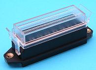
Similar to these?

-
No insisting on HSS at all, just learning with what I have available, which is predominantly HSS for the milling machine at the moment (except the face cutter), and a mix of HSS and indexable for the lathe.
Is there a definitive reference for cutting speeds? I've found a lot of conflicting information online.
I'm machining the back of the tool holder, not the tip itself.
-
Hi all,
I got my Bridgeport up and running again over the weekend, and tackled a project that has been outstanding for a while. My indexable tip tool holders are too tall, so my plan has been to machine approx. 0.3mm off from the back of the holders, to drop the tip height.
I tried using a 16mm HSS end mill at approx 50m/min (so approx 1000RPM). Feed rate was approx 60 mm/min. I'm feeding by hand.
What I found was that very quickly, the outside tips of the end of the tool went blunt. They didn't get overly hot, as there was no colouring of the metal, it was just missing!
I tried lubrication (light oil applied manually) and also a constant air blast to clear the swarf.
In the end, having taken the tips off two cutters (16mm and 20mm) I resorted to my 2" face cutter, which has done the job ok.
What am I doing wrong?
- Too fast?
- Too slow?
- Wrong use of the tool? (I've read that facing may or may not be right for an end mill?)
- Tool holder too hard?
Thanks,
Luke
-
Where did you get the dimensions from Ralph?
-
That's what I thought, but I don't know Mach3 in detail.
-
Mach3 one day! That sounds cool. Does Mach3 already have the ability to vary spindle speed?
Now, I need to test this, and get the right gear ratio factor between the inverter setpoint and the spindle. It's not far from 1:1 but it definitely isn't. I have a feeling the reference speeds for each material might need playing with a bit.
This is my first foray into Arduino, (as opposed to Microchip, raw Atmel AVR, basic stamp) and I have to say I'm impressed. Certainly takes the faff out of building a board and at less than 20 quid for the Leonardo it's a quick and easy way to get up and running.
Blue LCD is worth the extra few quid, it's certainly bright.
Luke
-
For tapping, I always use Trefolex
Old school and just works!Flip! I knew what I use, but couldn't remember the name, I googled it and Rocol sounded right, but it's Trefolex I meant! light green oily, paste-y stuff?
-
Here's the test rig

And here's the display showing the material type, tool diameter, setpoint spindle speed, actual spindle speed, inverter output frequency and motor current draw.
Here's a video to show it in action. -
Buy a tin of Rocol RTD compound. It works well for tapping and a tin will last ages.
If it really is a one-off job, I'd rather use engine oil than wd40, which will just run off. -
Inverter Drive Supermarket is useful for comparing prices, and they also have a helpful 'How to' section.
http://www.inverterdrive.com/HowTo/
For home applications, it's far simpler to have a motor that will run 230V 3 phase. This is typically found as a 230V Delta/400V Star configuration.
Using an old motor (old windings) on a VFD is ok, but if the motor is on its last legs, the PWM from the VFD can cause the insulation on the windings to break down, leading to shorts either phase-phase or phase-earth.
It may be that it is more cost effective to source a new IEC frame motor and adapt the mounting, rather than get an old motor re-wound, as was the case with my Bridgeport milling machine.
Sizing an inverter is based on two key requirements - the constant duty requirement and the overload requirement. Most decent inverters will have 150% to 200% overload capability, but the RMS requirement must be below the constant duty capability of the inverter. Some manufacturers rate their inverters based on low overload (say, 10%) and others allow a much more significant overload (150%-200%) so it is important to understand how the drive is rated.
On a lathe or milling machine, overload capability is only really needed for accelerating the spindle, so the overload requirement can be reduced by reducing the acceleration rate.
Conversely, a hydraulic 2/4 post lift requires a significant overload if the motor has to start on-load, so a drive with significant head-room is required. To compare with DOL starting, a motor might take 6-9 times its rated current as starting current - for a very short period of time. An inverter controls this far more elegantly, but a standard induction motor does not product any torque at zero speed, so there are some applications where you still need to get going with some grunt.
Luke
-
Wow, the dates on this thread make me feel bad...
Having run the milling machine on the VFD (sat on a bench) for a couple of years, I've decided I really should do something about it.
So, it's out with the old control gear. I'm pretty glad I've never used it, actually.

And a mock-up on a fresh new (ish) backplate.

Followed by some marking out, ready for drilling and tapping.

Meanwhile, one of these,

Along with some of this,

Means I've actually got a way to control the VFD, once it's tucked up inside its new panel, away from swarf and oil, etc.
Luke
-
For what it's worth, you can use jump leads or manually wire links to create the same circuit, in order to test the motor separate from the solenoid pack
-
Garden sprayer, drilled hole, tyre valve, air line tyre inflation tool, job done.
-
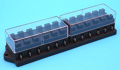
This gives you 12 fuses, if required, but it's longer. There are shorter ones available - 8 and 10 fuses.
-
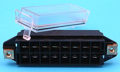
If you went with spade terminals, you could use one of these?


Heritage Car Insurance - won't insure a hardtop Defender 90?
in International Forum
Posted
I've got a quote from Adrian Flux, anyone else recommended?