


Jamie_grieve
-
Posts
465 -
Joined
-
Last visited
-
Days Won
4
Content Type
Profiles
Forums
Events
Gallery
Blogs
Posts posted by Jamie_grieve
-
-
Discovery V8's have them too.
-
Were you cutting welding and grinding something interesting?
-
This is a bit of a random one but I just bought one of these:

From Auto Star in the Czech republic.
They do mail order too I think but I had mine picked up.
the 786 Koruna's is just over £26. The four bolt mounting is easy and the bearings sit in an oil bath and it's the right kind of size of thing without being too big. It's from a Praga V3s.
As Steve says, having it positioned concentric with the link mounts will give the optimum amount of plunge and as long as the links are long enough to avoid the joint going much over 20º on droop or bump you'll be grand. The joint's will handle more but you should try to avoid it.
-
Summary:
It comprises a transmission system (3,5,6,12,20)
capable of adopting at least a first position,
in which establishes a first relationship of trans-
mission between an input shaft and an output shaft,
and a second position in which establishes a se-
second transmission ratio between these axes, is
inserted between the output shaft of the motor and the shaft
entrance to the gearbox, and further comprises
clutch means (15,16) adapted to allow
system over said first transmission
position to said second position and vice versa, and I-
control means (30) of said clutch means
(15,16).
Lets double the number of gears, and is applicable
ble to vehicles series so fast and easy.
DESCRIPTION
Particularly speed multiplier
for vehicles.
The present invention relates to a multi-
speed multiplier, particularly for
vehicles, comprising a transmission system
mission capable of adopting at least two positions
tions, a first position in which he states
a first transmission ratio between a shaft
input and an output shaft and a second po-
sition in which establishing a second relationship
transmission between these axes.
This device allows you to double the number
gears, and is applicable to vehicles series
fast and simple way.
BACKGROUND OF THE INVENTION
Mechanical devices are known, more or less
We sophisticated applied to changing sea-
chas of a vehicle to increase the number
gear, is well known, for example,
"Overdrive", which is mounted to the gearbox output
changes and provides a new combination
Gear leading to May 1
to
¯
or long-
permarcha.
These devices have the advantage of adding
a new transmission ratio between the axis of
motor and gearbox output shaft but have
several drawbacks that limit their application.
First, the known mechanisms
pose a number of problems arising from their
mounting the gearbox output. They tend to be vo-
light, and can not be installed in any
vehicle, in addition, allow the mayorıaunicamente
ten to add an overdrive.
The utility model U 201763 proposed a
multiplier mounted outlet box
changes, which doubled the number of marches
vehicle and which is satisfactory in some applications
tions, however, now been found that
can improve the performance and the compatibility
ity of known devices.
Description of the invention
The aim of the present invention is to propose
ner multiplier speeds not pre-
present the aforesaid drawbacks, which may apply
Carse any vehicle marches doubling
the same, and installation is fast and sen-
cilla.
In accordance with this objective, the multiplier
speed according to the invention is character-
ized by the fact that is inserted between the shaft
engine output and the input shaft of the box
changes of a vehicle, and further comprises
clutch means adapted to allow
transmission system over said first
position to said second position and vice versa, and
said control means clutch means.
The device offers a number of advantages im-
portant.
First, to duplicate all
gears of the gearbox, including re-
conductive in the case of 4x4 vehicles. This
lead to a much better poten-
tion engine, acquiring greater flexibility
When choosing a relationship. Eg
For overdrive, the device allows
30% increase to top speed, re-
ducing also the regime. Is therefore
reduces the emission of greenhouse gases, and
increases the life of the engine and its components
tees. Also helps reduce consumption
fuel.
Thanks to its location, can be installed
easily and quickly as a separate kit
tooth, between the engine and the gearbox
any vehicle. This location also makes
compatible with all types of gear boxes, re-
conductive, differential locks, etc.., making the
Maximum performance thereof.
Finally, note that deletes all
Typical problems of multi-joint mount
multipliers such as "overdrive" at the end of the
gearbox.
Preferably, in the first position the ve-
speed of rotation of the shaft of the gearbox
is higher than the motor shaft (upshift)
and in the second position the speed of rotation
both axes is the same (low gear).
The multiplier effect is thus adding a
longest running each of the marches of
gearbox.
In a preferred embodiment of the invention,
the transmission system comprises a corona
driven in rotation from the motor shaft,
a planetarium that is coupled in rotation with
the axis of the gearbox, and at least one
satellite meshing with said crown and said
planetarium, said satellite mounted on a
swivel.
Advantageously, the clutch means com-
comprise a first clutch when this em-
energetic blocks in rotation the turntable,
so that the rotation of the crown is transmitted
deeste the satellite and the planetarium, and a second
when this clutch clutch transmits
the rotation of the swivel to the planetarium
with interposition of a transmission element;
Control means the first clutch clutching
desembragan gue and second to obtain di-
said first position of the transmission system,
and desembragan clutching the first clutch and the
second in order to obtain said second position
transmission system.
This configuration has the advantage of per-
allows moving from one position to another, ie
long or short march back without disconnect
tar engine change (without pressing the pedal
clutch of the vehicle) so that the ma-
maneuver can be performed very quickly, without
slow down and without down torque to
zero, with the consequent advantages, for example,
under conditions of competition.
Also advantageously, the clutches are
panied multi-plate clutch in oil bath.
Thus, the clutch acts with more sua-
activity and is more durable and has a perfor-
nes far superior to standard clutch.
In one embodiment, the first clutch is
disks coupled in rotation with the support
satellite rotating and fixed disks, and follow-
second clutch is coupled disks
rotation with said support and engagement disks
two with said transmission.
According to a particularly
advantage of the invention, said satellite is a
eccentric wheel mounted only on the co-
rona and planetarium, which has a toothed
engaging the outer crown and a den-
internal state that meshes with the planetary man-
taking the wheel meshed with crown and
warming by two diametrically opposed areas.
This new configuration of the satellite man-
has the size of the multiplier at a level
adpatarlo allowing virtually any
vehicle in substitution by standard clutch.
According to one aspect of the invention, the means
control valve comprising a regulatory
and two cylinders that control solenoid
Hydraulic, each of which drives one of
clutches.
Preferably, said check valve and
said solenoid are governed through
a knob in the Cabin to pass up
short to long and back up, and through the
vehicle clutch pedal to disengage
the two clutches simultaneously.
Also preferably, the regulating valve
dora has means to cushion the manio-
bra of the two clutches engaged.
Thereby avoiding an abrupt clutch
of the discs when the driver releases the pedal
clutch.
BRIEF DESCRIPTION OF THE DRAWINGS
For more understanding of what has been ex-
position is accompanying drawings in which is-
schematically and solely by way of example
not limited to, show a practical case of
realization.
In said drawings,
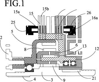
Figure 1 is a schematic sectional view
longitudinal speed multiplier
ties of the present invention;
Figures 2a, 2b are schematic
longitudinal section of a valve regulated
troller used in multiplier
invention in two operating positions
tion, and
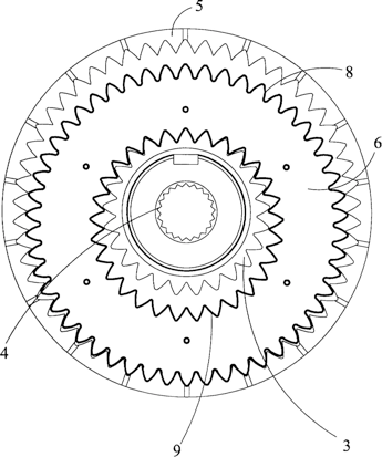
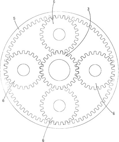
Figures 3 and 4 are schematic
cross section of two embodiments al-
alternatives gears of multiply-
dor.
Description of a preferred embodiment
Figure 1 shows schematically the ele-
Key elements of the multiplier according to the
invention. The device is mounted between the engine
and the gearbox, the clutch replacing
standard of the vehicle and the driver has
a controller for acting on the device.
The device causes, at the pleasure of driving
engine, a variation between the speed of shaft-sa
engine output and input speed cam-
Bio: As a result, each change relationship
(Each gear of the vehicle) is actually du-
complicated in a low gear, which coincides with the
Serial vehicle because the output shaft
engine and input shaft rotate at the change
same speed, and a high gear when the
driver operates the multiplier and the device
introduces a non-unity transmission ratio
between the engine output shaft and the input shaft
of change.
A drive pulley coupled to the shaft 2 is
engine output, and is input
multiplier, while a planetary three con-
tituye and the multiplier output is coupled
through a splined to the input shaft 4 (not
shown) of the vehicle gearbox.
The drive plate 2 is coupled to a co-
ring gear 5, which engages with one satellite
6 constituted as described below
with reference to Figure 3, a pre-wheel
sents both an external toothing 8 as a den-
internal state 9. The satellite toothing 9 6
turn meshes with a toothing 10 of the planetary
Three.
As best seen in the view of
Figure 3, the eccentric 6 is mounted satellite
respect to the ring gear and the planetary May 3
and always remaining wheel meshing entreestos
either swim in two diametrically
opposed.
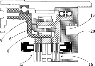
The satellite 6 is mounted on a support 12
with interposition of suitable bearings 13, the
also support 12 can rotate, driven by the
rotation of the satellite in June.
The device also has two sets
clutch plates are denoted with the reference
ing 15 and 16, respectively. Half of the
disks of each set, 15a and 16a, respectively,
mind, are integral in rotation with the support
Satellite 12, as shown in Figure 1.
The other half of the clutch discs 15
(Disks 15b) are integral to the housing of the device
positive (not shown), and are therefore
permanently fixed. Meanwhile, the other mi-
16b tad clutch discs 16 are requested
DARIOS a transmission element 20 that is
coupled with the planetary rotation through three
of a key 21 or striatum.
In the following description, the clutches 15 and
16 are called "long clutch" and "em-
clutch of short "respectively. This so-
tion is that, for each gear of
vehicle gearbox, when em-
panty disk set the planetarium turns 16
the same speed as the motor shaft, so
that the relationship is the corresponding transmision
to the vehicle gearbox (low gear),
whereas when engaging the set of
15 the planetary disc rotates at a speed faster
top, and the transmission ratio is higher
(Long March).
When the clutch plates clutching
of short 16, the rotation of the crown 5 is trans-
6 and allows the satellite to its support deeste 12 which
16 through clutch drag element
20.This transmission, in turn, drives in ro-
planetarium Tacion 3 after the union by cha-
vein 21. The characteristics of this chain ci-
nematic are such that the rotation speed
planetarium is like the engine shaft.
In contrast, when clutching disks
long clutch 15, the transmission is
from the crown 5 to 6 and deeste satellite direct-
Planetary mind to 3, since the bracket 12
satellite is locked in rotation by the em-
clutch 15 (as mentioned, the discs 15b
deeste are fixed to the housing). This transmission
introduces a variation in the speed of the pla-
Monetary previous case (Long March).
The clutch discs 15 and 16 are
panied in oil bath for more performance
smooth and to be more durable.
Speed multiplier described com-
also comprises a hydraulic circuit
pump (not shown) for two cylinders 25,26
actuation of the clutches 15 and 16, respectively,
tively, and check valve 30, repre-
Tada schematically in Figures 2a, 2b.
The hydraulic cylinder 25 is fixedly mounted
multiplier housing while the ci-
cylinder 26 is secured to the transmission element
20 and rotates therewith.
The check valve 30 shown in FIG-
Figure 2 is designed to allow control of the
clutches 15 and 16 to go from short to long or
vice versa, via a button or a drive
Similarly, and also when you want to disengage
to change gear, pedal through
vehicle clutch.
For this, the valve 30 comprises a housing
house 31 in which are formed a series of ga-
Lérias of oil pressure and return connections
and are in communication with a housing
axial 32 which slides a rod 33. Between
the rod 33 and the housing 32 is interposed
a slider 34 which is externally one
plurality of recesses to allow, depending on their
position along the housing 31, open selectively
tively the passage between the different galleries.
Around the stem 33 are mounted one
valve spring 35 and a spring dispenser 36
whose mission is to give more or less pressure. On-
spring is mounted between two floating one Spanish-
ciador 37, which acts as a stop to prevent com-
Excessive spring pressure dispenser 36. A
shutter 38 closes the front of the housing
tion 32.
In the housing 31 is further formed a CA-
cavity 39 adapted to accommodate a solenoid
conventional (not shown) which controls the
Oil supply to the cylinders 25 and 26.
Figure 2a corresponds to a normal position
poorly functioning, ie, a position of
valve in which one of the cylinders 25 or 26
maintains the corresponding clutch engaged
15 or 16 (depending on the position of said
conventional solenoid), and the torque is
transmitted to the gearbox. Depending on
which of the clutches 15 and 16 is attached, the
be long or short march.
To change gears, for example 3
to
¯
to 4
to
¯
, The driver presses the clutch pedal
gue, which causes thanks to the configuration
the check valve 30, the drive if-
simultaneous of the two cylinders 25 and 26 and the unem-
clutch of the two sets of disks 15 and 16, of
so that the gearbox is disconnected
Tada engine, as in the case of a clutch
traditional, and the driver can change sea-
cha.
The rod 30 is coupled at its end
free the vehicle clutch pedal: when
the driver depresses the pedal, the rod 30 is
shifted from the position of Figure 2a to the
Figure 2b position, dragging the
slide 34, thanks to the presence of a plug
40 which is threaded to the end of the slider 34.
This movement of the slider opens the passage
oil between some housing Galleries
31 so that the two hydraulic cylinders 25
and 26 are actuated simultaneously to release
rar disks of the two clutches 15 and 16: in
Consequently, the drive shaft is disengaged from
gearbox, and the driver can change
gears.
When the driver has changed sea-
cha and stops the clutch, this re-
its initial position by the action of a corresponding
tooth spring (not shown), dragging with-
I keep the rod 33 back to the position of
Figure 2a, however, thanks to the provision
Springs 35 and 36, this movement is made
gradually, so that coupling is avoided
ing abrupt clutch discs between
other.
To move from one place to the corresponding short
sponding high gear, the driver must sim-
ply operation of a control, for example a
button which may be located on the lever
change: this drive through the
check valve 30 and the conventional solenoid
tion, change the position of the pistons of the ci-
cylinders 25 and 26, so that clutch discs
gue of short 16 are disengaged and discs
Long clutch 15 are clutched, at
which varies the speed of the planet and
Consequently the output of the gearbox,
passing a short march to the same gear
long, or vice versa.
Importantly, it is not necessary
press the clutch pedal for this step of
long or short to long to short: it has
logically the advantages of allowing manio-
bra faster and the torque does not drop to
zero during the maneuver.
Figure 3, as noted, represents
cross section position and configuration of the
Satellite 6: in this preferred embodiment, the satellite
This consists of a double-toothed wheel
8 and 9, mounted eccentrically to go rolling
between the crown and the planetarium March 5.
This structure has a number of advantages:
First, to limit the dimensions
multiplier, and thanks to these small di-
dimensions the device can stay without pro-
replacing the conventional clutch problems
of a vehicle, in addition, thanks to the diameter of
satellite, engagement with the crown and Planetarium
is carried out on a high number of teeth, ga-
suring quiet operation and a
minimum vibration.
However, the transmission between the crown
5 to planetary 3 could be done with a plu-
rality of satellites conventionally as
shown in Figure 4: in this case are mounted
Four satellites 6 around the circumference
3 planetarium, all coupled to a so-
support 12 as described for the realization
above.
Another possibility is to perform the transmission in-
between the drive pulley and the output shaft through
a gear train, instead of a system
crown, and planetary satellite in this case, one
gear be mounted on the support
Although herein is
been described and shown an embodiment with-
chalk device according to the present
Page 6
1. Multiplier speeds, particularly
mind for vehicles, comprising a system
transmission (3,5,6,12,20) able to adopt
at least two positions, a first position in
which establishes a first relationship of trans-
mission between an input shaft and an axis of sa-
output, and a second position in which he states
a second transmission ratio between these
axes, characterized by the fact that in-
inserted between the output shaft and the motor shaft
input gearbox of a vehicle, and
further comprises clutch means (15,16)
adapted to allow passage system
transmission from said first position to said-
second position and vice versa, and control means
(30) of said clutch means (15,16).
Two. Multiplier according to claim 1, character-
characterized by the fact that in the said primary
mere position the shaft rotation speed of
the gearbox is higher than the axis of the mo-
tor (Long March) and in said second position the
speed of rotation of both axes is the same
(Low gear).
Three. Multiplier according to claim 1
or 2, characterized by the fact that said
Transmission system comprising a crown (5)
driven in rotation from the motor shaft,
a planetarium (3) is coupled in rotation
with the axis of the gearbox, and at least
one satellite (6) meshing with said crown (5)
and with said planetary (3), said satellite
mounted on a swivel bracket (12).
April. Multiplier according to claim 3, character-
characterized in that said means
clutch comprising a first clutch (15)
that when this clutch blocks in rotation the
holder (12), so that the rotation of
the crown (5) is transmitted to the satellite (6) and deeste
the planetary gear (3) and a second clutch (16)
when this clutch transmits the rotation of
said holder (12) to the planetary (3) with
interposition of a transmission element (20),
and by the fact that the control means (30)
clutching the first clutch (15) and de-clutching
the second (16) to obtain said first position of the transmission system, and de-clutching the first clutch (15) and the second clutching
(16) to obtain said second position of
transmission system.
May. Multiplier according to claim 4, character-
characterized in that said clutch
gues (15,16) are multi-plate clutches panied ba
in oil.
June. Multiplier according to claim 5,
characterized by the fact that the pri-
mer clutch (15) has a disc (15a) coupled
Plados in rotation with the turntable (12)
the satellite (6) and fixed disks (15b), and said
second clutch (16) has a disc (16a)
coupled in rotation with said support (12) and
disks (16b) coupled with said
transmission (20).
July. Multiplier according to any of the preceding
claims 3 to 6, characterized by the fact
that such satellite (6) is mounted wheel unaunica
tada eccentric relative to the crown and the planet-
rio, which has an external toothing (8) in-
meshes with the crown (5) and internal teeth (9)
meshing with the planetary (3), keeping
engaged with said wheel and planetary corona
two diametrically opposed.
August. Multiplier according to any of the preceding
claims 4 to 7, characterized by the I-
fact that the control means comprise a
valve (30) and a solenoid that
control two hydraulic cylinders (25,26), each
one of which actuates one of the clutches
(15,16).
9. Multiplier according to claim 8, character-
characterized in that said valve
regulator (30) and said solenoid are governed
swim through a command in the Cabin for
shift from low gear to high gear and vice versa,
and through the vehicle clutch pedal
to disengage the two clutches (15,16) if-
simultaneously.
10. Multiplier according to claim 8
or 9, characterized by the fact that the valve
regulatory (30) has means (36) for love-
tiguar engaged maneuvering of the two em-
clutches (15,16).
6
× for all claimsClaims for n◦:Realization of the report dateExaminerPage29.09.2000L. Ruiz Lopez Ayllon Tower1/1 -
Wow indeed, good job!! Exactly the thing I had in my minds eye only better thought out and better than I could ever have come up with. Not before time either, poor Bill must be on his 101st cup of coffee by now nutting this out.
Does the link below show an English translation to the drawings?
-
so it was blasted then I did a minor repair patch then it was dipped and chemically stripped, it then got zinc plated and ended up looking galvanised, I was hoping for bling gold colour! seems to have done inside as it was totally submerged in the tank
Mike
That's exactly what I did with mine too. Submerging it in the tank doesn't make any difference, the acid dip cleans off the rust but electroplating doesn't take place inside tubes or long cavities without stringing electrodes inside. You might actually find you have lost corrosion protection around the vent flaps and in the middle of the door pillars and are simply relying on the depth of coating on the outside to sacrificially protect the inside. That's why I filled mine with paint and rolled it about.
-
Does the electroplating process get the rust out of the cavities?
Yes, the chemical dip before the plating process does but one problem with electro plating is that it doesn't do inside box sections like hot dip does. I had my Austin Gipsy bulkhead electro plated and it has been good but not as good as dipping it would have been. I could have cured any distortion far easier than the rust when it comes back. The dip cleans everything back to bare metal then how do you paint it? I poured paint into it and bunged the holes up with paper and rolled it about the place but I wish I'd got it galvanised. I also wasn't aware of the zinc paints you can get when I did it. Galvafroid poured into an electro plated bulkhead might work. I painted the Land Rover bulkhead I made with it and it's amazing after being left out in the rain for the last 4 years it's still hardly got a speck of rust on it.
-
I'm very much liking what you're doing here but one observation if I may is that some of the wiring might not be up to the standard of the rest of the work which to the untrained eye lets it down a bit. There are some conventions too such as black for negative and red for positive which although are just conventions they are generally followed pretty much everywhere. The photo of the alternator showing the red earth cables are what brought it to mind. That being said, maybe it is positive earth?
I'll be very interested to see how this progresses. If you do ever get it on a dyno, please make sure to record the figures from idle up and not just from 1200 or 1500 rpm as I believe it will be right at the bottom end where this conversion will shine.
Did you record any transmission oil temperatures before this new modification?
Good job so far, what's next?
-
It can be done in a weekend with help & preparation
With the best will in the world, there's no way unless he was doing it on a daily basis and knew every bolt size, location and colour of every wire I would tell the OP he could change a chassis AND bulkhead in a weekend. How many additional hours to strip the roof, front wings off, windscreen hinges, clean and make the windscreen frame seals again, swap the heater, wipers, dash, brakes, doors, windscreen washers, floor panels, tunnel front panel, vent flaps and seals and screens, heater controls not to mention the siil panels and channel you would normally leave in place. Then you have to line it all up again on reassembly that you normally don't have to do.
The point I was making before is that there's a huge difference between changing a chassis or doing it with a bulkhead. Just changing the chassis doesn't involve dismantling the whole vehicle structure and controls and yes, it is possible in a weekend with a bit of planning, I'm not going to disagree with that but telling the OP who I'm guessing hasn't changed a chassis before that he can do it in a weekend I don't believe is that helpful to him but rather misleading him into thinking there's not that much to it.
-
It's late and I'm thinking out my ass a bit but how easily could a planetary gearset be arranged where the clutch normally lives, maybe with a hollow sun gear as a quill shaft connected to the clutch plate driving a set of planetaries living in the bellhousing finally driving another hollow gear going through the quill shaft and splined to the gearbox where the middle of the clutch plate would normally be. This bit might have to double up as a release bearing too. The clearances on the spur gears would maybe want to be considered due to the relative movements of everything concerned This could give an alternative set of ratios and be made in such a fashion to be bolted in and out of a standard transmission maybe with just an alternative clutch plate and little modification to the bellhousing. Does any of that make sense to anyone not sleeping?
-
If you are using Volvo axles with a disc brake conversion you need to be aware of the location of the bearings in the hub and that the normal Volvo wheel is inset, not offset as any normal 4x4 wheel would be and the corresponding effect of the king pin inclination on the scrub radius and your chosen tyre size. You will have to derate the axle accordingly depending on the offset of your wheels. If you run wheels with a large offset you also run the risk of breaking the front swivel housing just above the bottom king pin if abused hard.
-
Good story, I just use my name, I don't have anything to hide, no Iranian nuclear secrets, missile codes, how to make cold fusion or anything interesting at all really. A computer trawl isn't getting my bank details or address out of my name and even if it did it could just look me up on my profile or Face book and get in touch with me there. I've helped loads of people out over the years because they could get a hold of me fairly easily and kinda know who I was. I use radio call signs at work but they're just alpha numeric mostly and not cool enough for an illustrious forum such as this!! I'm maybe just not 'cool' enough for a nick name, I can't really think of one that suits. Another advantage of using ones name or at least being consistent is it was great to 'meet' Bill and a few others on here from other places.
-
Normally you lift the body off complete and as said, you can swap everything over in a few days but as you're changing the bulkhead that is almost as big as changing the chassis and requires a complete strip down. A good rattle gun to take everything apart will honestly save you days as will cutting off anything stubborn and then deal with the fixing with the better access you'll have with the chassis out of the way. Make sure the rivnuts for the steering column are in the new bulkhead and tapped out if you do get it galved before fitting it. Putting in a good bulkhead will add years to the life of the vehicle. As said above, have new fuel and brake pipes and flexi pipes to save hours of messing around and not forgetting the clutch flexi if the auto bit wasn't a typo and maybe a new speedo cable. Now's the time to run any winch wiring or cutoff switches / security dooh dahs. Use grade ten bolts with coppaslip and don't use stainless on anything load bearing but good for the floor fixings into those plastic things. An impact driver on the door hinges is about right if they're worth saving and a long wobble bar is great for getting the wings and down pipe off. I'd change the hinges and look at new studs where the down pipe bolts on to the turbo when you've got easy access. I wouldn't hurry it as it sounds more like a rebuild than a simple rechassis and give myself an easy month of it after work and suchlike and allow plenty of time to get any bits you need. I'd also say whatever you think it's going to cost, I'd add an extra grand onto it for all the things you decide you need before it goes back on the road.
Good luck!
-
There is no frame flex at all, its a box chassis with a multipoint cage tied into it.
Looks strong, well built and ought to be fairly rigid. I only mention it as it would be unusual in something so short and with that type of construction but in the first and last photos where you can see the top of the cage it looks slightly twisted down at the front at the driver's side and down at the passenger side at the rear corresponding to the movement of the wheels and the crossmember with the towball on it doesn't look parallel to the top tube either again corresponding to the wheel movement. Might just be an optical illusion with the way camera lenses work too maybe. All frames flex a bit if they're made from metal and have a torsional load placed on them, just some move more than others depending on the design.
-
Looks nicely balanced, how much droop / bump at static ride height? interesting to see how much frame flex there is too for such a light vehicle.
-
Down to the bare rims I guess, its a bit uphill though, AND theres a bit of a step up in the entrance. I have visions of it spinning and making a LOT of noise. And sparks !
Ifor williams trailer wheels fit if you want it really slammed.
Maybe I should have explained a bit better, trailer wheels have a 12" rim which is really small like a mini but with the same stud pattern as a Landy and with a tyre on ends up as small a thing as you can put on without driving on the discs. No sparks or spinning as you correctly guessed driving on rims.
Still got the bother of changing them too. A battery rattle gun might be on the cards or install an AC compressor and tank to run an air one.
Why rent such a small garage if you're into Land Rovers and are probably aware of how reliable they aren't?
-
Ifor williams trailer wheels fit if you want it really slammed.
Convert to air? -
The Defender ones are handed and sit at different heights and don't have as much rubber in them as series ones. I'd say if you're inventing things to make fit then the series ones would be easier to work with.
As John has done, Bearmach or other reputable source is the way to go and save yourself the pain, suffering and misery of something in a blue box.
-
You could do as Cwazy Wabbit suggested but I would just stick a speedy sleeve on there if it really had to be repaired.
I think in the UK with easy access to spares replacement would be the best option.
-
Stick a series starter button in and forget all about the solenoid would be another way.
-
Jaime, do you know what the kenworth suspension used to prevent the chains from coming off when the axles articulated at angles independent of the single central drive axle?
I've no idea, I don't get it at all. The torsion bar setup is clever but I don't see how the articulation was achieved without any clever chain stuff going on.
I haven't been all the way through it but if you find the answer, let us know!!
http://www.kws900.com/other/CHAIN_DRIVEN_TANDEM_BEAR_AXLE_VEHICLE.pdf
-
Chain size depends on the sprocket size, most chain drive equipment doesn't really have more than 3/4 chain but uses big driven sprockets to reduce stress. The old Kenworth in the photo probably has about a 20" sprocket or tumbler as they were called on crawlers. I used to drive a KATO HD 750 excavator with a worn out chain drive. It was a disaster when it jumped off as it was always when it was under pressure climbing up or going down something. The chains and sprockets out of an old Argo cat might be handy for you if you found some bigger sprockets to be driven or you could get the complete chain drive and bogie from an old grader if you need something heavy. What you thinking of building?

-
Looks like a DAF 328 would yield most of the bits for a full size version.

-
Here's something to keep you amused o_teunico,
You may find that mobility scooters are subject to different regulations in your oppressive regime that would allow you to get silly with your ideas.
http://www.youtube.com/watch?v=owFRcin2zqw
http://www.youtube.com/watch?v=I-BQ9sRxGoQ
http://www.youtube.com/watch?v=8A8AGEwATBs

I'm trying really hard not to make one with portals and a V8!!
centre bearing advice
in Modified Vehicle Builds & Special Projects
Posted
I'll grab some yoke dimensions when I'm down at the shed tomorrow. The Transit centre bearing would be fine if the shaft was misaligned by maybe up to 10º at best, after that the resistance by torque on the splines during plunge or extension of the prop would have a rubber type of centre bearing wrecked in no time and possibly introduce launch shudder. To be fair, the Praga centre bearing doesn't really use up much more space than a prop shaft, less actually cos it doesn't move and it keeps the shafts properly in phase. Remember if you use a single joint in the middle like a Transit the diff pinion must be the same angle as the centreline of the fist shaft not the transfer box but if you use the Praga type of centre bearing then the transfer box and diff pinion should be parallel.
How do the Hilux guys do for long travel setups, I think they also have a centre bearing and might have a neat solution?