


De Ranged
-
Posts
1,022 -
Joined
-
Last visited
-
Days Won
5
Content Type
Profiles
Forums
Events
Gallery
Blogs
Posts posted by De Ranged
-
-
sounds like a good portion of these mods are what I'm planing on doing to the next one .... Sll 109 tow/camper wagon DD
Nissan TD27 Ti from a Terrano ll with auto
range rover rear axle from my toy truck (shaved n braced)
Disk brake front end on series axle
Power steering
extra door on passanger side
New front seats from a holden callia
sound proofing
carpet and insulation
New dash and console
extra fuel tank
draws and fold out bed
water tank
electric windows
etc
not planing on starting it till after back opp
-
your articulation causes bump steer, so would be surprised if it passed for road legal, better off to look at the new euro cars some of them run full hydro or electric steering ... that is legal so steel that system
Unfortunately our rules for modifications are very clear that you need a mechanical connection for the steering....yet these new cars are coming in and driving on our roads... lol hopefully the rules will be updated
-
I have a bar at the shop that is for using a set of bathroom scales so the scales take from half to a fifth of the weight.... allows me to do corner weights problem is they compound there margin of error, I tuned them with 4 20l oil drums filled with water.... its not perfict but at a guess I'd say my margin of error would be around the percentage of the fraction i'm measuring on, so at 1/2 I'm +/- 2% at a fifth Im +/-5% and I can measure slightly over half a ton with them
the tractor method isnt very accurate because you get the body roll so on most trucks will give you a false reading higher than it really is
-
Now I read somewhere that COG is COG and making the track wider will not lower it. It will reduce the tendacny to roll over at a given point but not lower the COG? is this correct?
Yes, centre of gravity is all about weight and where it is.... you can change the shape without changing the CoG, the only time you change CoG is when you move weight(adding your bullbar and winch or cutting down your deck, or extreme like my planed changes to lift the gearbox on my toy)
Imagine a triangle, the wheels are the base of the triangle and the Centre of Gravity is the top, to tip it over you have to move the top point out past one of the outside wheels.... there are a few other things that effect things, spring rates, body roll etc that move the CoG towards the downhill side so in reality you will tip sooner than the triangle will suggest lol
body roll is an interesting one and a main part of that is roll centre height, if you can get it to the same height as your CoG the only body roll you get is from the springs but.... this wont tip you, remember I said you could change the shape without changing the CoG yep lol, the distance between Roll Centre Height and the CoG acts like a lever to tip the triangle over before its reached tipping point if the CoG is above..... now whats really cool is if you could get the roll centre height higher then your body roll would act like a lever to stop you tipping.... I have seen some rock crawlers setup with very high panhard bars to try and do this with not that much gain... the reason why they didnt get much gain is it is down to sprung weight vs unsprung weight now for us with a truck our unsprung weight is 20-25% of the vehicle weight so we have 80-75% of the weight acting on that lever thats why we tip before the triangle happens. Now that rock crawler with over built axles and water in his tyres and no body just a light cage frame his weight ratio is 70-80% unsprung weight with only 30-20% acting on a lever and because the lever is short (its very hard to get above your CoG) the effect wasnt noticeable
why I love suspension lol you have to understand the whole before the individual pieces make sense
I've done a bit more research on the 110 CoG.... interesting what you find in forums, Uninformed did you ever tip your truck over with the tractor lol
I did find a PDF that looks like coach builders plans, looks genuine with a stated 655mm CoG
working off a CoG of 655mm and standard unmodified weight, anti dive works out at 198% with your mods adding a 7% increase to the same score of 213%
been trying to find data on a RRC as a comparison as well, as I used to have one and remember what the handling was like
but that one will have to wait till Ive got time lol
-
arghh there is the issue from what I found on the net CoG was 1060mm on the defender.... just on a side note this shows the difference you get just from the least accurate variable lol
Your CoG figure did you measure or was this the top bolts of the bellhousing method, or some other source
-
thanks for that Uniformed, I calculated it without the lift so I have a base line to work off
Done it for you 144% anti dive.... with out the 2 1/2" lift I worked it out at 130%
this is based off internet data for weight put it at about 2130kg with the listed mods just out of interest have you measured.... I left the CoG standard height, the mods would push it down to offset the lift
anyone else interested
hmmmm
-
yes your right,
I was half thinking about what I was planing and Im so used to ploting links not radius arms lol my bad I over complicated things
those three measures will do
I'll have a go at them tonight cheers
-
Why do you need the length of the axle mount/s to the chassis mount?
because the angle the arms are on changes the amount of anti dive, that measure + the height to the chassis mount lets me plot the angle which runs from the center of the axle to this point
It will also let me calculate roll axis angle... something that I think is more important than most realise, but is a subject for another thread
-
First is there anyone out there with any doubts about what Ive put forward.... even if you'd just like me to rewrite anything
Assuming all is good then....
the way I see it... if I'm going to set a figure (for me to build too lol I dont mind walking the talk) we need some data.... what is a standard radius arm, and anyone out there with something different but still on radius arms
Need some states from you
Tire size, Wheel base, model (will let me look up center of balance and weight), distance from the center of the front wheel to the chassis mount of the radius arm, next the distance between the mounts on the chassis and on the axle (from the centre of the link to the center of the other link) and the last measure the height from the chassis mount from the ground
And anything odd.... tray back, rollcage anything that changes weight or any of the above measurements
Now the subjective part.... if you've got a bit of experience, if the front climbs well
I'll work out what your Anti Dive is and post em back up
-
The output spline for the 700 trans is 27 spline major dia 29.8
Hope that helps
-
No problems, Im just about to head in to the shed...
-
LOL I'm not trying to scare him off, this isnt personal for me, up until this thread Id never considered this.... I want him to tell me where I'm wrong, If it is something I feel he is wrong about then I will try and find a way of proving this lol I dont play "he who is loudest or most negative", if in doing this I prove him right I will happily post up this, I want to get this right because I'm dead serious about building my front suspension based on what I see..... now I dont want to waste my time
I see all of these forces working just like Ive tried to put forward... I can see reading back where my terminology could let things down and the offer stands to edit it and I suspect that is all it is, but if I'm wrong on something then that needs fixed
Now for those of you who dont know, John (bush65) seems to know one of the better suspension experts from the old days of pirate, that and his age warrant hearing him out, I'm just hopping he will step up.... if at the very least to clarify my posts so that they are understandable lol
I'm sort of stuck at the moment... if some of what Ive put forward is wrong then advancing from this point is well pointless lol
To me the next logical point of discussion is how much Anti Dive to aim for with a link system that is fixed to the axle and the compromises
PS hey Don are my posts really that bad lol do I need to go back through and edit them....
-
I would say I have a different approach or mindset
since I had my first car I have changed, fixed or modified every vehicle I have owned (including my heavy equipment lol).... what better to have than a Landy, a vehicle with so many quirks and issues that need fixing lol
I havent even got the motor in the one I've got (let alone the trans, axle swops, power steering, competition guards, roll cage, rear mount radiator, new front suspension etc)
and Im already sorting out what Im going to do to the next one... and sourcing parts & the truck lol
-
I appreciate your interest in making this public, so far you have given posts with broad generalisations that you know something that I have gotten wrong ... stop pussy footing around and tell me what... so I can do something about it lol... you go on about being all concerned about how I have made mistakes and the damage it could cause yet you come back with another generalisation you do understand this doesnt make you look very credible
stick your neck out and tell us all what I have wrong lol
Come on John we want to learn....
-
Chris turned up again so let him loose with the plasma.... the two X members above are gone along with the engine mounts.... next job will be to grind up the left over bits the plasma didnt remove... but I might have got a job for young chris so this job will be mine lol
Back was pinging me a bit so I decided to do some machining on the lathe, I made up the tool holder for the cutter I'm going to use to cut the dog clutch splines.... just a bit of dumb luck on our version of ebay I picked up a cutter that matches the profile of the splines
The holder tool is made from the first version of the carrier shaft lol
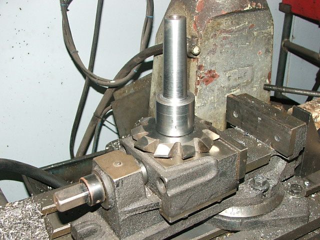
All setup ready to mount to the mill
-
Thank you for taking the time to type that lot out, Peter
-
I was taught that the CO2 will make for a slightly stronger weld due to some of the carbon being taken from the shield gas and slightly deeper penetration, the weld will be less visually appealing being a tighter more upright bead and there is more weld splatter
I've never heard of pub gas before, to me I'd be concerned with the volume of other gases in the shield as this isnt industrial gas to set standards, its a food gas they are worried about other contaminates... my concern would not be Nitrogen it would be Oxygen and Hydrogen... one makes the weld porous the other makes the weld brittle and neither of these would be a concern in a food gas
I personally run argoshield less splatter and a flatter weld
to the above post the freezing of the reg is because of a change of pressure the reaction is endothermic.... the shielding of the weld is not a change of pressure so no reason for the gas to take heat out of the weld
to gain the slight advantage in penetration I would say that the CO2 is burning slightly hotter
-
lol I'm not leaving, but bush65 does have a point.... my terminology is all over the place I'm pretty certain that fixed and floating axle thing is a term that only MTBikers use and then just the down hiller's lol but it was the easiest way for me to describe my point, now if there is something else I've miss named that has the potential to cause problems... a thread with this many responses will be top of the list for internet search engines, that means I could screw up alot of people who are doing research into AS/AD.... having been one of those I understand how "muddy these waters are" and how frustrating it can be lol
so for the moment I will wait, I have sent a message to Bush65 asking for help to sort any issues.... I have the same feelings as bill, I dont mind egg on my face so long as Im learning lol
Now as a side note, I am confident enough about the forces in action even if I've messed things up, that Im going to fit a version of radius arms to the front of my toy, packaging wise the one link doesnt work
Now back on thread in that video, at one point mog rover does try very near the line the zuk took but the front end slid off the rocks at the top instead of climbing over this did get them over in the end, the back end didnt react like it was getting any grip
My guess is the tyres were what let them down maybe older tyres or a hard compound or a tighter pattern.... thanks to the mud i cant see enough to make anything other than a guess lol cool looking truck tho
-
I had this after I did my tank with POR 15, it turned out to be a little bit of paint in the end of the plastic the screw holes that were too shallow I put a little drill bit into .... used a bit of tape on the drill bit and set it in one of the good holes then drilled to the same depth .... problem solved
-
De Ranged, I can't hold off any longer from not saying this, your incorrect use of terminology and physics annoys me, to the point that i have to turn away from reading your posts. Sorry but I guess that is because I'm a pedantic old so and so, but it is engrained from years of having to watch out for and correct mistakes before harm results.
My apologies.... my suspension knowledge comes from experience across different sports and motor sports each one has its own terms sometimes at odds with others, I'm also not good at explaining things... I tend to think things through faster than I type so I tend to miss or short cut things lol one of the reasons my mates dont like me explaining things to them ... if you feel this has the potential to cause harm I will back out from these discussions
If there is anything in particular you are concerned about Im more than happy to edit it out
-
Dont forget to undo the wires on top, in my case the earth wire ran straight to the chassis you'd only get a couple of inches before your hanging on it
-
Just for the books I got a D pass in bursary physics.... oh how I wish Id applied my self in physics and maths lol
If it helps most of my friends now make a point of asking what to do, and state they dont want to know why..... yea Im not the best at explaining things lol
-
Yep you are dead right that is how you work out / adjust AS/AD I'm not talking about that
Right lets just talk AS to simplify when you get acceleration you get a weight transfer in resistance to this (inertia) now as the inertia effects the back suspension it causes it to sag the harder the acceleration the more weight the more squat.... AS will resist this (sorry if this is over simplified Im not trying to be insulting its just easier to show this way) now the way it resists this is by transfering a percentage of this force into the links, I know on pirate eveyone assumes AS is an upward force... not quite right
At 100% all the inertia is balanced in the links so your back end doesnt sag, there is no extra weight to push the springs down.... if you doubt me test it
find a pot holed dirt track some where that you are going to leave wheel tracks, coast over it at say 30km/hr now if you walk it you will see your tyre pattern it should have rolled in and out of the pot holes..... now try the same thing accelerating as hard as you can odds on your tracks will not have dropped in to the potholes as much now this is assuming an average car with say 50% AS if you can do this with some thing setup with more AS anything that is setup to do drags you may find that the accelerating tread pattern may not even drop into the far side of the pot holes
This is due to your AS loading up the links this extra mass unbalances your sprung to unsprung ratio, your shock valving is now wrong and the extra mass makes it harder for your spring to move the axle down into the potholes
Now all that makes sense yes ? if it does then apply that to my first paragraph
Now to the second bit about fixed or floating Im a bit peived photobucket wont upload pdf files now I drew up a rough diagram to show this, looks like I'll have to describe it lol
My point wasnt if a link system will pull the front down, it was what link system was best at doing this
Now a fixed link like a radius arm or 1 link that is attached to the axle if the axle wants to rotate then it has to rotate the links... so the counter force of the wheels rotating forward on the front axle wants to make the axle housing rotate back wards rotating the link down simple yep
Now when you have a floating (if you were to disconnect the links from the chassis they would fall down they don't lock to the axle) system the rotation of the diff is countered by the separation of the links at the axle by the top link forcing towards the chassis and the bottom link pulling on the chassis... where is the down force lol.... there is still a force because the links angle towards each other they have an instant center now the closer this is to the axle the more force is going to be turned into downward force.... but it will never compair to a fixed link system for this effect
I hope Ive described it in a way you get what Im thinking
-
The front axle rotates (rocks) backwards when driving forward and rocks forward when in reverse gear, so when driving forward the radius arms, One Link, or 3 link, if the upper and lower links projected lines converge to an instant centre will produce a downforce at the front of the chassis.
Yea thats the obvious one equal and opposite... wheel goes forward housing has to rotate back to resist .... just on a tangent this is an interesting one to try and take advantage of this, you want your chassis anchor points to be as close to the front of the vehicle as possible
No what I was thinking of was
First does AD really accentuate this effect so far we have one person who has anecdotal evidence.... but by my understanding of the forces is that AS or its reverse AD transfer force from the springs to the links, the greater the % the greater the amount of the force from the de/acceleration is transfered to the links.... now that means that high AD will indeed increase this effect .....
Now next point the difference between floating and fixed suspension (this is something I picked up from MTB design lol) now your 3 or 4 link has a floating mount I'll get into this in a min right the fixed (one link, two link, any thing that is fixed to the axle to rotate with the axle) the links become a lever to in effect pull the front down
Now a floating mount (3 or 4 link, where there is a parallelogram effect )... since this style vectors the force up through the links any gain from this would also be vectored...... which would make it less effective
so what ya reckon am I right ?
If so this could explain why some have already proven radius arms on the front keep the nose down when climbing lol
Looks like I'm going to have to make a 1 link or 2 link work for my truck ....
this only applies to us who are 4wd front and rear beam axle LOL, I know what you mean uniformed... it took me ages to work out that the majority of suspension books are for independent axle suspension... and all those taken for granted forces dont work the same for us lol mind you at some stage Im going to have to go back and read em again so I can sort out independent suspension for a hyabusa powered offroad racing buggy I've got in the plans
PAS pump/box combo for no bump steering
in International Forum
Posted
No these arnt issues if your scrub radius is small.... you need that "beef" when you run oversized tyres with offset for more width this increases the scrub radius which means more leverage on the steering system
I'm with bill on this, steering linkages down low is just lazy and it was one of the things I wanted to change with mine
Nice idea for the tie-rod but that is something we arnt allowed on road here lol, and for offroad na lol it'll still get caught... notice all the missing paint on the underside of the axle higher than where the new tie rod is....