


David Sparkes
-
Posts
2,530 -
Joined
-
Last visited
-
Days Won
4
Content Type
Profiles
Forums
Events
Gallery
Blogs
Posts posted by David Sparkes
-
-
Under FTC3375, LRWorkshop show it as M12 x 1,25; 35 mm ; 20 mm thread; steel 10.9; double hex. (I would call the head 'bi-hex), but no matter).
LRW also state the current number is SYP500090 and while that gets results from more suppliers, I haven't found one that mentions the thread form.
You have managed to unscrew at least one, surely you can measure the pitch yourself (1.25mm)? If not, it's a good prompt to buy a thread pitch gauge.I see that under SYP500090 they are available as sets on eBay, but appear to be much more expensive per bolt than buying from a LR Supplier.
Regards
-
What is the LR part number of the bolt?
Regards
-
The link did work for me, using Windows 10 and Mozilla Firefox.
Regards.
-
I can see that the terminology is difficult. It seems that Draper (at least) call the 'non-electrical' versions 'impact screwdrivers'.
I can't recall whose make I bought all those years ago, but I do agree with the advantages of the hammer blow giving positive engagement as well as the turning force.
If you have had good service from a Draper version in the past then their range seems a good place to start. Once you have a part number you can use it to chase down the best price.This search seems to produce their range.
Regards.
-
7 minutes ago, walace58 said:
The Range Rover Classic and the P38 were sold concurrently possibly from during 1993 to 1995. I do not believe the P38 is termed Classic. So you need to identify what Model of Range Rover you are discussing, either the original classic shape or the P38.
My thoughts exactly. After my previous post I looked back at earlier posts from Polly123. The 38A was consistently referred to, as was the BECM, so it looks as though his vehicle is a 38A.
As part of my earlier post I did some Google Search research, and this happened to turn up that Workshop manuals on CD for the 38A are now readily and cheaply available.
Here and here are examples, I have not used either supplier.
I used the search terms 'workshop manuals P38 cd', there were many other returns. Note that a list of parts will be another purchase; they don't come on the RAVE CDs.Regards.
-
A 1994 model is now termed a Classic Range Rover, so all my comments regarding the later 38A model do not apply..
I can't advise the best place to find wiring diagrams. There may be paper versions around, although I can confirm there was a RAVE disc produced later that covered 'Archive' models, as they were called. This included the later versions of the Classic RR, as well as the Discovery 1 and the Freelander to model Year 01.
Whether searching generally on eBay, Amazon, or independant LR suppliers, the key word to include in your search term is 'Brooklands' as they do the reprints that include 1994 and '95. I got no results that suggested Haynes books went to '94.
The snag is the price; expect to be asked around £60 for for a new Brooklands reprint.I am assuming these 'Workshop Manuals' include the wiring diagrams. The term I used, ETM (Electrical Troubleshooting Manual), came in with the RAVE CDs, and the 38A Range Rover.
Perhaps there are people on here who have bought copies in the past.
Regards.
-
I guess you are asking about a 38A, post 1995 RR.
I suspect the button has failed electrically, or perhaps the wiring in the tailgate. I don't know how you opened the tailgate manually from the inside (what year is your vehicle?) but I think you are going to have to remove the trim on the tailgate to fault the electrical circuit or button.
The alternative is a wiring fault before the tailgate is reached, and a fault here may also affect the fuel filler flap.
I'd say that normally this wouldn't affect the immobiliser,but I seem to recall the power to the tailgate comes via the drivers door lock switches.Have you checked the RAVE ETM wiring diagrams for which fuses are used, and whether any connection plugs are common to both circuits?
Regards.
-
Looks like your original thought has stood up to the challenge of our second guessing! 🙂
Good luck.Regards.
-
1 hour ago, elbekko said:
Pretty sure the P38 was almost fully developed before BMW had anything to do with it.
Very definately, the 38A was developed by Land Rover in the early 1990's, being released for sale in 1995.
The BMW involvement was because theirs was the only diesel engine with the required sophistication for the target market envisaged by Land Rover. History shows it wasn't perfect, but at the time it was the best available.
The engine ECU lives in a high position in the engine bay.
All the other ECUs were placed by Land Rover. It was an LR decision to have a single central BECM to which 'all' other ECUs reported to. Time has shown that was a blind alley and it became better to have a common means of intercommunication (such as CANBUS) rather than a central ECU.Regards.
-
You have a PM from myself.
Regards.
-
5 hours ago, tuko said:
My 88" is built on a Designa coil sprung chassis that has a Designa custom fuel tank which is in the range of 43ish litres.
... Or have suggestions or tips or ideas that would extend my range with the 88".Todd.
I don't know the Designa chassis, or it's 'custom fuel tank', but I thought standard tanks used to be 10 Imperial Gallons, or ~50 litres, so that makes the Custom tank smaller than normal.
The modification I do recall is to replace the standard Series underseat tank with a Defender tank, which extends forward underneath the RH floor plate. There is some loss of ground clearance, but I'm not sure how much this will affect you. The 12 imperial gallon capacity primarily makes use of the space between the standard fuel tank outrigger and the standard bodywork outrigger ahead of it.
The standard forward outrigger for the Series fuel tank needs cutting off, and the bolt-on Defender item (possibly from the LH side) needs bolting in its place.I thought I had a section with all the parts especially listed, but I've hidden it somewhere, so have had to go back to the standard list. This is a pity because I can't pass on the specific recommendation I had seen and recorded. So it seems all I can do is pass on the idea, you will have to do your own checking on parts availability etc.
Fuel tank was NTC 2008, with its internal fuel pump PRC7419 (or NTC2519 pickup unit if you have an external pump you can use) and fuel level sender unit (two options based on chassis VIN, so I can't even guess which would suit your circumstances.
The front mounting bracket is NRC 9474.
Double checking has found two 15 gallon tanks, both listed as an 'extra fuel tank', NRC 7040, and NTC2889, changing at VINs 243342 and 3.
Both use the front mounting NRC6829.
The early one uses an external pump, the later one uses an internal fuel pump PRC7018.If you can fit in a 15 gallon varient that gives you at least 50% greater capacity, possibly just using dead space.
If you weren't already using the LH underseat space for a battery etc a second Defender tank could be fitted there, giving a total capacity of up to 30 Imperial gallons.
Are you sure sure you can't put your electrical bits and pieces in the dead space you found? 🙂Regards.
-
49 minutes ago, FridgeFreezer said:
I'd hope the LPG injectors that are part of an LPG injection kit are up to the job of injecting LPG

I'd hope so too; they must be a development from after my involvement, which thinking back, was getting on for 10 years ago 🙂
Regards
-
58 minutes ago, Bowie69 said:
I forget the complication, but there was one....
Having been interested in running injected LPG at one stage, I know of one complication.
It centres around lubrication of the injectors. As I understand it the fuel passing though the injector acts as a lubricant; while diesel is good, and petrol is OK, liquid LPG is not.
Obviously it is a problem that is overcome with CNG, but no doubt at considerable cost, well beyond the scope of backyard amateurs.Regards.
-
2 hours ago, Gazzar said:
Is slag a profanity? What does it mean?
Good Grief; this is boring.
There are no doubt other dictionaries, but at the first instance try the Online Slang Dictionary entry for slag; see if you can follow the links.Regards.
-
 1
1
-
-
From the V8 supplement to the main S3 workshop manual, the torque setting for the stub axle bolts is 30 - 38 lbf-ft.
Regards.
-
 1
1
-
-
For my blast cabinet I used a FIAC Miami for several years. It matches the specification of yours, twin cylinder, 3 HP, BUT as you can see from the attached brochure, the no-wheel support has a rubber foot. I had no trouble with the unit dancing across the floor, so I would simply add a rubber foot to your existing unit.
Regards.-
1
-
-
A complete change of subject would be better catered for in a New Topic.
However I see that while you are new here you have hadthe courtesy to include your location, something a lot of people forget.
That being so, I had to look up Tambellup.I am not familiar with ETC5155 but from the picture on the LR Series web site I am assuming the upper face of the nut contains the locking element.
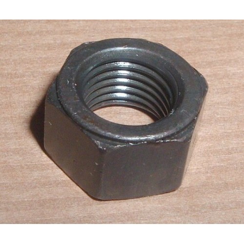
In common with other locking nuts I've used (Nyloc, K'line, Aerolock) the nut is placed with the free running section first and the locking section last, away from the item being clamped.
If the nut does run on completely freely, with no stiffness, I don't know the answer to your question 'Which way does the shoulder go, against the bearing cap or away from it?'Regards.
-
It was many years ago that a colleague, on a different forum and now out of touch, installed a camera in in the horse box.
In his case it was the only camera, but the connection was via Bluetooth. I don't recall exactly what he used as a screen, phone, tablet, or dedicated screen.
I do recall there was a battery involved, which didn't last the complete trip (I don't recall how far), and that his wife was most taken by the way she could talk to the horse (there was no 'answer' facility). The camera did allow them to see when the horse kicked the box, and produce a working solution. (It was a two horse box carrying one horse, with the central partition in place. When cornering forces became too high the horse tried to spread its legs for greater stability and thus kicked either the side of the box or the partition. Apparently the cure was to remove the partition, the horse was then able to stand more comfortably).
So, I suggest Bluetooth is your option to connect to the camera, however connected I can suggest nothing about integrating an additional camera into your existing viewing facilities.
Regards. -
When I saw the picture the initial thought was control of the electric AC fans from Series to Parallel and back, but they used relays anyway.
I don't recognise the plug, and can't be bothered to read the ETM connector diagrams - that would be cheating anyway.'Common failure point in early vehicles', well mine was a '95 (bought by me in '99, so I missed the earliest years). Even so, nothing really sprung to mind, but reading on most things have been eliminated by others.
Thinking for a little longer, the only item not mentioned by others, which did have several revisions in the life of the car, was the electronic control for the Hi-Lo shift motor. The facility, if not the ECU, is common to Auto & Manual gearboxes
I started writing this and nothing else sprung to mind, so that's what I'll vote for.Regards
-
1
-
-
Quote
Any suggestions please?
Yes.
Start by resetting the steering correctly, ths is easier with both wheels off the ground.
Because there is a known fault related to the steering relay, disconnect the steering box from the relay. Preferably that's the end of the longitudinal link from the steering box drop arm, although it may also be necessary to disconnect it from the relay itself, so you can ensure both ball joint threads are free, the joints themselves are not worn, and the rubbers are not split. Just in case, be aware that the longitudinal arm has a LH thread at one end and a RH thread at the other, this is so you can adjust the lengh of the arm without disconnecting the ball joint tapers, but merely by releasing the clamps at each joint, then turning the tube. Note that there is no facility (flats) for gripping the tube, it has to be the bodgers delight, stillsons or a self grip wrench.I'm understating the difficulties here; the clamp bolts will be rusted tight, and may shear, the TREs will be rusted in place, and the tube will not be in the mid position, Rather one joint will have been screwed fully home and the length adjusted by the mechanic breaking the ball joint taper at the other end, screwing the TRE out to the position he wanted.
Now turn the steering wheel from lock to lock, counting the turns. Divide by two and turn the shaft to the central position. With a felt tip pen mark the end if the steering column with a mark, centre to 12 o'clock or centre to 6 o'clock. If the wheel is in the position you want it, remove the nut holding it in place and put a matching pen mark on the steering wheel boss.
If the wheel is not placed where you want it, remove the wheel, rotate and replace it as required, always ensuring the steering column mark is vertical.
After this is done, recheck (full lock to full lock, counting the turns, then counting turns back to the mid position).
A piece of masking tape around the rim in the 12 o'clock position makes it easy to check if the wheel has moved, being visible through the windscreen.
Now the alignment of the wheel will show the mid position of the steering. If the steering wheel ever becomes misaligned (not where you want it) NEVER change the position of the wheel on the shaft. Look for the fault in the steering linkage and repair / adjust as required to get the steering wheel in the mid position.Now look at the position of the drop arm on the steering box; it should be pointing directly (vertically) downwards. If it doesn't, reposition the drop arm. HNJ make a reproduction special puller to help removing the drop arm, if this is too expensive look for 'pitman arm pullers' to do the job. Space is at a premium, so don't go too bulky.
With the drop arm vertical recheck the steering wheel is still in the mid position.Now ensure the relay arm is in the place you want it, and reattach the longitudidal link, adjusting the length so it is a drop in fit. Recheck the steering wheel hasn't moved.
Note that the figure of 81 degrees is a clerical error, dating back to when the book was written. There are 44 splines on the steering relay shaft, with both sets of splines being in alignment with one another. It is impossible to arrange the relay arms so they are 81 degrees out of alignment. If you choose the 'not 90 degree' setting the relevant arm is moved one spline.
With a S3 the radiator grill panel should have slight protrusions on the lower corners, these provide space in the rear of the panel for the relay arms to be set to 'not 90 degrees' and still achieve full lock without the relative TRE striking the panel.Once you have set the relationships of steering wheel to steering box drop arm to relay arm correctly, the rest is relatively straight forward.
The snag here is that you cannot rely on previous mechanics getting the original settings correct. People tend to take short-cuts, introducing mistakes.Regards.
-
42 minutes ago, FridgeFreezer said:
There's at least two different lengths of otherwise identical-looking clutch release bearings and getting them mixed up is very easy and can give either no clutch at all or permanently disengaged clutch, could be an easy fix. ...
I haven't had time to look the details, but I'm pretty sure the pressure plate can come with a steel ring interface between the spring fingers and the release bearing.
If I've interpreted the pictures correctly, there are pictures of the 'old' pressure plate with no steel ring interface.
If my recollection is correct this might be a cause of a 'wrong' release bearing being supplied.
Stressing the 'not checked' status, perhaps this improved pressure plate would have been used for a 2.5 NA engine, or even a TDi engine?
I will have to leave that open for comment by people with hands on experience.Regards.
-
1 hour ago, David Sparkes said:
...Use the ETM to identify the wire colours, then jumper in an independent 12v supply.
42 minutes ago, elbekko said:You mean the ones that are all white?
Dunno, it was all too long ago to remember specific details, but I thought my 95 had wire colours, because I identified picking them up as a way to power a car in a scrapyard that had no battery. Not that I ever did it in practice.
Anyway, you have hit the essential, use the ETM on the RAVE discs. I presumed Simon has them as hardware copies or software downloads.
Regards.
-
In my limited experience, it's the button itself; as the locking mechanism is in the tailgate rather than the door frame there is no easy electrical bypass, neither is there a manual release cord.
Your could try pushing the button harder than normal, or pushing it in quickly and forcefully with the heel of your hand.If this works your immediate next step is to remove the trim from the lower tailgate, so that you can 'easily' access the wiring. Immediate means before you close the tailgate again.
If forceful manipulation of the button doesn't work you have to fold the rear seats down, crawl into the loadbay, and work out how to remove the tailgate trim while the tailgate is still closed.
I've never attempted this, so cannot give any further direct advice, though it is a job I have to do, so feedback will be welcome 🙂If for any reason you think it's a lack of power to the tailgate you have to lift the carpet in the load bay to expose the wiring trailing over the floor (RH side IIRC).
Use the ETM to identify the wire colours, then jumper in an independent 12v supply.Regards.
-
My first move would be to go back one step.
Either disconnect both propshafts from the transfer box (best move) or simply put the transfer box in neutral (Hi-Lo red knobbed lever to the mid position).I'm starting with the principle that mechanical devices don't like sitting still for a long time; they seize up.
Of particular relevance is the friction plate rusts to the flywheel.With the transfer box in neutral you can start the engine with the main gearbox in neutral and see if the handbrake drum turns slowly as before, and if it is as easy to stop as you recall.
You can also preselect any gear, then start the engine, and see the results on the handbrake drum.
You can then see (hear) what happens to the engine note when you apply the handbrake.
Ideally, I'd like to see the handbrake stall the engine if 4th gear was preselected, but the handbrake might not be strong enough.Now with a gear preselected, press the clutch as far as it will go and start the engine, probably the handbrake drum will turn. Now apply the handbrake; this will stress any rust joint between the friction plate and the flywheel; it might let go with a bang.
You may still have to release the gearbox and slide it back an inch or so. This will facilitate operating the clutch release bearing, isolating the problem to the pedal or hydraulics, or the clutch plate itself.Regards.


Sandblaster
in Tools and Fabrication
Posted
If it's steel & rust you are cleaning (not aluminium sheet, or glass) treat 60 psi as your minimum pressure, If it drops below that, stop work until the receiver fills to maximum pressure.
Do not have any sort of filter on your 'hoover', the target is to maximise fresh air throughput; any filter will block with dust and restrict the flow.
Ventilation to remove dust is an entrirely different subject to pressurised air carrying the blast media. Ensure you have a large hole to admit fresh air; ideally place this hole so the fresh air entering the cabinet washes over the inner face of the viewing window.
Have the inlet to the extractor fan below the height of the mesh worktable; this will ensure the dust moves downwards away from the viewing window.
Florist film is good the protect the viewing glass, but you still need to draw the dust away from the film.
Grimy surfaces, and thick paint, absorb the energy in the grains of the blast media. Clean off as much as you can before putting the unit in the cabinet. Leaving thin paint is OK, it's the five coats of brushed on paint that need prior application of paint stripper.
Regards.