


Team Idris
-
Posts
1,606 -
Joined
-
Last visited
-
Days Won
5
Content Type
Profiles
Forums
Events
Gallery
Blogs
Posts posted by Team Idris
-
-
I hear the argument against the sun gears, and its fair. So I put forward the use of a standard landy clutch plate;
Weld the diff up so its just a 90 degree 3.5:1 gearbox. Fit the input flange with a metal disk 3" larger than the standard clutch pressure plate of your choice. Fit the outer rim of the disk with a brake caliper (winch brake). Drill the disk to take standard clutch parts with release bearing, and link it to the caliper. (quite a linkage task I know). This gives good leverage on the caliper due to diameter and because its before the gear reduction,.
Using a hydraulic caliper may make the linkage simpler, as the master cylinder can be connected directly to the clutch fork rod. That makes the brake self adjusting, which solves the problem of wear with mechanical linkages which need constant adjustment.
If 3" on top of the clutch diameter is way too big, maybe a car clutch plate would do? Or, maybe the brake would have to be on its own because of diameter, in which case, bolt the disk to the diff pinion, then a short shaft to clear the caliper and then fit a flywheel?
-
The one on the yard crane had two band brakes. One was brake, the other clutch. When you moved the lever you started engauging the drive just as the brake came off. It needed adjusting every so often.
So you fit a disk brake on the drum side (brake) and one on the other side of the diff (clutch). Once the PTO is in, the disk spins freely in the clutch-brake while the drum brake is held with a spring. Move a lever to overcome the spring, releasing the drum-brake and stopping the clutch-disk-brake, which forces the drive out through the sun gears. Proper Old School

-
Phone Break for a moment there
I sell all sorts, from little intecal type up to 2m square jobbies for 425hp CATs in 55 degree ambients. But selling these industrial grade rads into this market is hard, as the prices are a bit scary. You've got to really want somthing tough!
Why havn't I got one? Well, back in the day, I put my copper and brass rangy rad in the back. Now the milemarker is intergrated into the chassis, I havn't space up front.
So well worth a look at digger coolers if you want somthing abuse friendly.
Or, if your just on the edge of overheating, put an electric fan on the front of the rad to shove more air through and help the engine fan
-
Ditto on the digger core, even the drifters are fitting them!
Plate-and-bar coolers are a lot heavier and given the right tanks can do 500 psi all day long. (Ideal for taking a kicking). The advantage is thicker fins with a simple, easy clean geometry, coupled with fins inside the tubes for better heat transfer
Normally less efficient than ally car rads, you need more thickness. But fins are available all the way out to 8mm pitch (4mm gap) and square looking from the front. Very easy to clean and hard to block.
-
I put a T joint in by the last washer jet on the transit and ran a length of pipe up the RH wiper arm (open, no jet on end). You'ld think all the water would disapear up the 4mm nylon pipe, but no, the standard jets work as normal.
I had an alterior motive to my 'mod'. Dirt in the lines kept blocking the jets. I expected the 'tap' to let the dirt out. It did ! I left it on. (Permanent tempory fix)
-
Ah but, necessity is the mother of invention.
I can't get a second hydraulic winch through the house keeping as a 'necessity'. Hence the need for invention
-
Are we saying my tds goldfish will be quicker if I put a big resistor accros the field windings then? Because thats a lot more feasable than 24volt, and the motor should last better.
Or are we saying, "you go test it steve" and you can tell us about the attending fire engine afterwards ?
-
My mate's S1 has won prizes and is as genuine as you'll find. Over the years its had gearbox, engine, and axel changes. Its just had a new chassis. So really it is a rear tub from 1956. It's not a hybrid though. But not as 'original' as my 1992 RRC challenge truck with a landy body, which retains its chassis number.
Very difficult to draw the line between original and repaired and upgraded. I guess thats where the points scheme came in?
-
SU carbs, I mean, blimy, how steep do you want to go
 Any more and the gearbox is going to stop sucking oil
I think people take off some old worn out SU's, put on EFi and pronounce how much better off they are?
Well, you would be wouldn't you. Bad fuel mix is bad fuel mix

-
I was wondering the same thing last year. If the field winding was 'shorted' with a restistor load, what would happen.
1. Motor goes slower as current in the field is reduced, so less turning force?
2. Motor goes faster, as the reduced field strength reduces back EMF allowing the motor to run faster?
Don't know, and havn't tested it..........yet
-
Aha, took a while but I got it! Its the drive for the oil pump in the form of a dummy distributor drive
For foks who wouldn't butcher the old one, or, hell, just leave it on
 (Probably just me really)
Thinking laterally, If its spare, I wonder if it would do as a dry sump drive?
After months of making mine fit down the side of the block, I almost wish I hadn't thought of that

-
I've just re-built my 3.5 RV8 and it was quite expensive, as I did the vernier cam/chain, Piper max-torque cam, and ARP mains-n-head studs. But that should be a good engine now, with many failings addressed.
It is a re-build of the V8 I bought in to replace my old engine. And guess what? It was stuffed, so still needed the full monty. I say 'better the devil you know'

-
Good choice
I did a lot of reading and found the LT95 didn't like snatch towing in reverse! Which was pretty much what I had seen in my box
Bomb proof going forward though I'm offroad only, but I'm loving the V8 and auto. With good quality oil the ZF4 can take some abuse. I've seen off both front and rear diff crosses with mine. I did the front one while stationary, so plenty of low down torque
-
I've had rubber on there for a decade or so. Mucho stick offroad.
One problem was the inlet/outlet being so close together, so I had to file the hexagon off one fitting into a square! And a male/female 3/8" sweapt elbow helps get you away from the return hose.
One of my threads was the same as UNF bolt, but was still available after a hunt.
I recently fitted a 3/8" quick release so I could check the pressures, but that may be a bit too far for road use?
-
Heat soak argument is arse. It only applies to undersized charge coolers. I've just been sourcing flat bed coolers to cool V16 Perkins gas engines, which have charge coolers either side of the engine and run at full power constantly
The charge cooler is great for the Td5, as the turbo and inlet manifold are on different sides of the engine, so the charge cooler fits nicely on the front of the engine.
The turbo lag is reduced with a charge cooler.
A full width intercooler puts heat load on the rad, so the charge cooler is an opotunity to get rid of the heat somewhere else.
A charge cooler is smaller because one of the fluids has a much bigger j/kg.K than the other, as you guessed.
A cubic meter of air weighs 1kg, and a litre of water weighs 1kg, so the real gain is in the density of gas vs liquid.
The charge cooler is slower to 'saturate' which means the benefit of cold system lasts longer. It's acts like a bigger thermal capacitor than an intercooler.
Who uses them?
Charge coolers are great on supercharged V8's, as they slip nicely into the inlet manifold.
Anyone with a turbo or supercharged rear engine, as the charge air temperature can be passed to the front. (done parts for a porsche and a Lotus)
Anyone who wants less lag but still wants a low temperature charge.
Draw backs;
Double handling the heat in two fluids does mean the charge temperature will be slightly higher on average, by maybe 3-5 degrees.
You're in R&D territory with the Td5 charge cooler
-
Thats not the first auction. There was one years back! John sure has had a large collection
-
I recon your using other transfer box parts to save cost, but if you do a hydraulic drive option (Spline output), a hydraulic motor 'input' would be handy. I'm impressed with the Icelandic ones for crawling
-
I think Zim's gone off the idea
It's gone awful quiet ? -
Fan's either side or rad is fine. They don't see each other through the fins. It's a simple fix for a bit of cooler boosting.
I would think the oil cooler will also be okay, as only low engine power will be needed at low speed?
Outer electric fan is likely to be noisy, but they seem less harsh on the ears the bigger they get. My 8" spal is evil ?
-
-
Yeh, I like that. I'd only got as far as Jenolite in a jam jar. It's good, and no salt residue, but wallet wise its definately a jam jar operation

-
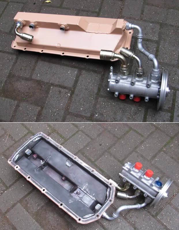
Okay, back on track. Might have some sump photo's for you soon Zim
.The RRC axel is far enough back, (or engine so far forward) that the axel tube cutout in the trough doesn't go right to the front. So the front scavenge point can be on the end of the trough. This is so close to the pump pack, that a solid pipe can be made up using off the shelf sweapt bend 90 hydraulic pipe fittings.
I had baffles in there acting as dams and structural bracing. The front one has gone and the rear one drilled through. The 5/8" fitting that was a few inches from the back of the sump will be capped and a new one has been welded in right at the back. When it nose up its all on the rear pump, and when its nose down its all on the front scavenge. The internal lubrication on the pump is all that that will keep it wet from now on.
Its now designed to work as a true dry sump, as in nose up or down, all the oil can be drawn off. Admittedly at 10 degree nose down, half a pint will build up behind the axel cut out.
Just a jockey pulley, a load of pipe work and a tank fab before it's ready to start them
-
If it's going to be hard to do, I can recomend the engine driven pump up front. Better for winch-n-drive
-
My original folded sump design isn't quite working. The front axel can come up a long way before it starts on the bump stops, so that classic dry sump 'trough' will have to be cut off at the front end. And the RPI studs stick out so much they are horribly close to stopping the sump going on
 . It's all a bit vexing
 Any more and the gearbox is going to stop sucking oil
  (Probably just me really)

 . It's all a bit vexing
I think thats definate "Its Broken Sir" call
in International Forum
Posted
I stripped a tripple shaft ZF down from a Duetze tractor. One gear is on a taper shaft. I had to cut this one off, as it was friction welded to the shaft!
But I've never seen anything that bad