


landy_andy
-
Posts
378 -
Joined
-
Last visited
-
Days Won
10
Content Type
Profiles
Forums
Events
Gallery
Blogs
Posts posted by landy_andy
-
-
5 hours ago, landroversforever said:
Is that how the chevvy TREs normally fit? They don't look like they will cope with much misalignment?
The Dodge knuckles are a bit thicker where they mount, if it binds I’ll get the back faces machined down a bit.
-
 1
1
-
-
New reamer arrived & I modified the knuckles for the Chevy TRE’s. Will use some rubber sheet to make the dust seals.
.JPG)
The ‘Freddilink’ arrived and wouldn’t fit the stock Chevy drag link, even though it’s advertised as being for it... so, reamed it out deeper too and am getting the back machined for clearance.
.JPG)
-
So nice to be able to start assembling stuff 🙂
.JPG)
-
3
-
-
Was looking around for other parts & found these specifically designed for the Chevy Moog TRE’s that lots of people use in HD steering here... 😁
.jpg)
-
Back onto the front axle to work on the steering. After looking at the two options of tie rod ends or heims, I decided to use the common Chevy 1 ton TRE’s for ease of replacement if necessary and tube bungs are widely available. Also, it keeps the steering looking more ‘factory’.
So, I think they’ll make a definite upgrade over the stock LR ones 😉
.JPG)
The Chevy TRE’s are the same taper (1.5”/ft) as the Dodge ones but are a larger diameter, so the knuckles need drilling out to 5/8” for the thread & the taper will need reaming out to allow full engagement.
.JPG)
Steering link will be 1.5” x .25” wall DOM with bungs and the drag link will attach with one of these that has a Chevy taper in it.
.jpg)
I also picked up a couple of the ‘anti wobble’ kits that are designed for Dodge TRE’s as they have to be bent out to clear the diff and it helps with steering link rolling.
.jpg)
My steering link will need bends in both ends to clear the lower shock brackets and with a bit of trimming they should fit and keep it all nice & taught.
That’s it for now... waiting on more parts to arrive... tic toc... 🙄
-
1
-
-
Made up & welded on some bosses for the brake lines, time to give it a good clean & coat of paint now ready for final assembly. Little transport trolley works great and will make swapping axles over easy.
.JPG)
-
1
-
-
Whilst waiting for parts, made a moving frame using some of the spare axle assembly jig parts. Just need casters to arrive to finish it off now. Will make moving them around under the truck much easier come time to install.
.JPG)
-
1
-
-
Axles I picked up for $65 each on Amazon... just got relisted at $194 each.... 😁
-
1
-
-
18 hours ago, uninformed said:
It would be interesting to see the profile of the super duty axles, im guessing only be 10xx material but probably forged and in the dia you will have, most likely fine.
Axles I picked up are 4340 CrMo, around 1.5” in diameter, will just need the end cleaning up to cut the 35 splines & polish a section for these inner axle seals.
.jpg)
-
17 hours ago, RedLineMike said:
youre progressing much better than i am with these axles im building,
not sure if its just the angle of the picture but the axle casings look very narrow,
The WMS-WMS of the axle is actually 3” wider than stock, the inner C’s and knuckles are ~12” from end of axle tube to wheel mounting face compared to ~8” for the LR axle. Main reason I’ve had to mount the spring perches partially onto the top of the inner C, makes the case really short.
Have to remember these are off 1 ton axles that are around 75-80” WMS-WMS depending upon make & model, mine is 64.5”.
-
1
-
-
Assembled up the front axle with the new spindles to get a rough length for the inner axle shafts.
.JPG)
However, am now thinking I’m going to have to buy the drive pucks to set the correct location of the outer drive shafts to get the centre line of the UJ on the knuckle steering axis centre line. Did ‘eye ball’ it with a steel ruler and measured both short & long side. Unfortunately, neither are ‘stock’ lengths from the lists I got off Pirate 🙁
Couple of options, buy custom ones out of the US at $400+ a set or get some Super Duty ones cut down & resplined.
Whilst searching for part numbers of 35 spline inner axles I found Amazon had some of the USA Standard Gear ones (~35” long) for $65 each... bargain 👍
-
1
-
-
Got the front hubs completed apart from a lick of fresh paint. Waiting on a set of Trail-gear HDPE spindle bushes before I can mock-up and measure the inner axle lengths. Am hoping that we can find some stock ones that’ll fit rather than going custom.
.JPG)
First parts for the rear third have arrived, spool and a 3.50:1 ring/pinion set. As the exchange rate to the US sucks, having to shop around on EBay and use not ‘made in USA’ parts.... to be honest, I don’t really care as long as they perform and for what I’ll be doing, they’ll work just fine.
.JPG)
-
2
-
-
Measured up the new lower radius arm mounts and ran the numbers in the link calculator. Dropped the anti-dive down to 118%, much better than the 190% with my existing setup. Roll axis will change a bit once I get the axle under the truck and figure out the track bar frame side mount.
.JPG)
-
1
-
-
Working on drilling out for the new lug nuts...
.JPG)
-
Front hubs back from m/c shop, holes plugged & ready to be redrilled to 5 lug. Spindles bored for the 35 spline stub shafts 😀
.JPG)
Makes LR ones look so skinny !
.JPG)
-
1
-
-
Picked up the second batch of cut parts yesterday, the first got cut in 1/2” material.... oops, the second set were correct in 3/8”.
.JPG)
Got them all welded out, finished the 3 link cross member.
.JPG)
The lower link frame bracket locates into the frame radius arm hole and is secured with a 1” bolt.
.jpg)
Will need to use the spare 1/2” spacers machined to a taper to fill the gap between the frame lower face and the link mount for the two 1/2” bolts that prevent the mount rotating.
.jpg)
-
1
-
-
19 hours ago, monkie said:
That is a real nice piece of work, it looks really neat and 100 times better than my old loom. I really like your idea of using a piece of board to lay it out on. I will certainly pinch that idea. Thanks for sharing
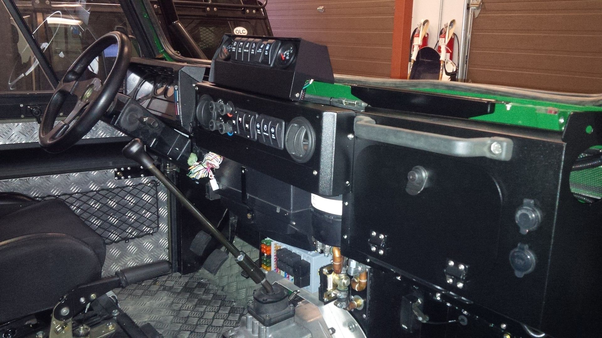
Thanks.... pity it’s all hidden behind my dash 🙄
-
1
-
-
- Popular Post
- Popular Post
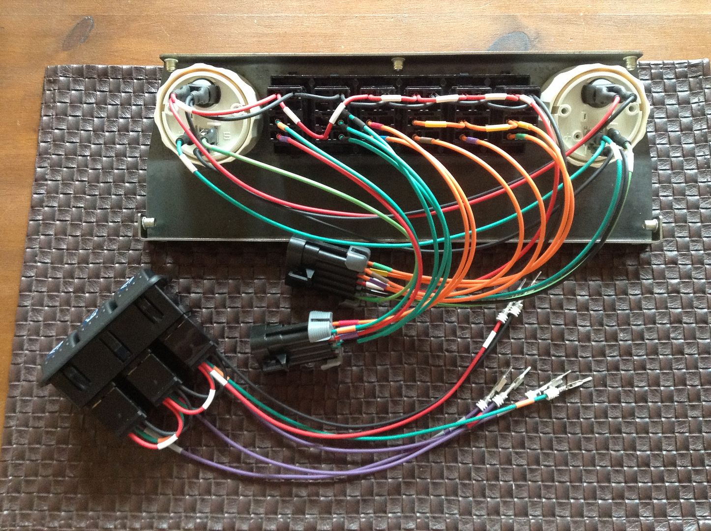
Here are a few pictures of how I put my new loom together for my D100 project, twist ties from the supermarket work great for making up the looms.
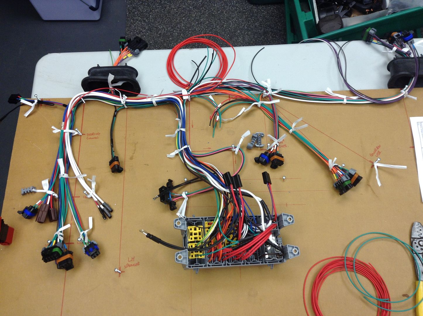
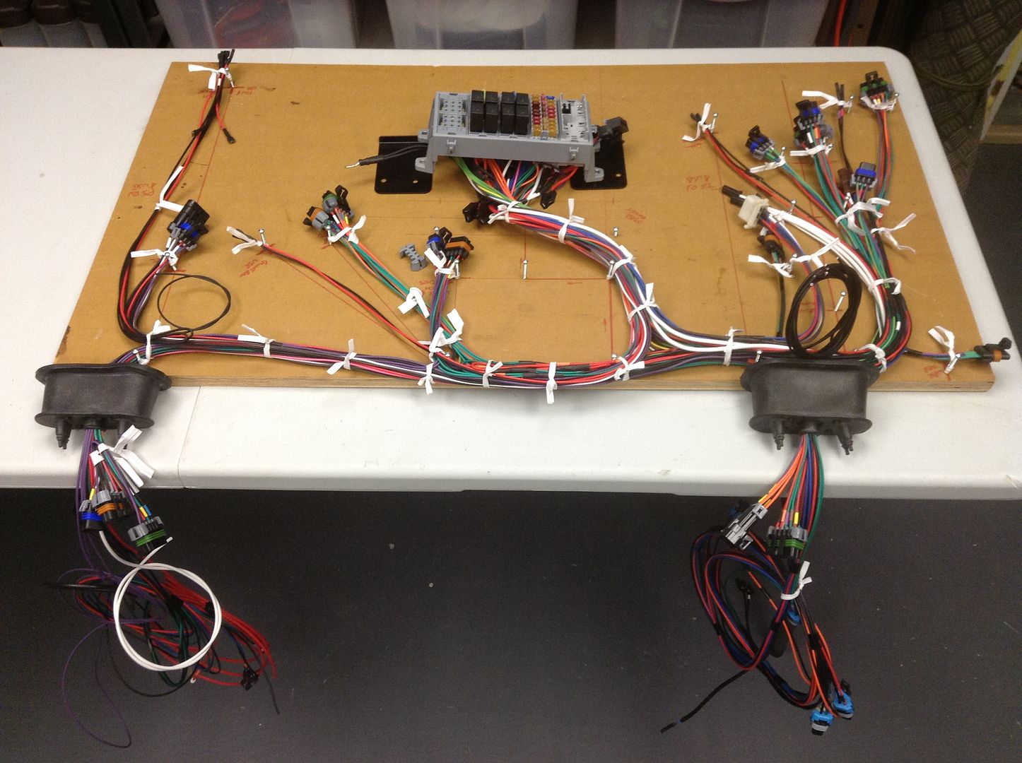
As I couldn’t get GXL & TXL in colour traced short lengths, I used solid colours with a heat shrink band on each end to follow the original loom specs.
-
6
-
Dxf’s emailed out to the water jet company, sit back & wait now for an email to go fetch them.....
-
1
-
-
After some more deliberation with a few cold ones.... quite a few 😜
Figured if I extend the horizontal plate out I can tie it into the lower face of the frame rail where the radius arm mount is welded on and use a captive bolt plate inside the frame via a drain hole.
.jpg)
.jpg)
This should hopefully prevent any rotational or shear loads affecting the mount.
-
1
-
-
Got the new lower link frame mounts drawn up. Couldn’t find an easy way to tie into any other existing holes so will give it a go as is.
.JPG)
.JPG)
These will give us this in the link calculator.
.JPG)
The anti-dive is an improvement over the existing setup of 190%. As always when your having to work around fixed points and trying not to rebuild the truck again, packaging becomes a compromise of ideal numbers vs practical solutions.
Once I get them fabricated up I’m planning on borrowing the truck lug nut torque wrench from work... click those 1” bolts of at 500lb ft 😀
-
1
-
-
2 hours ago, landroversforever said:
I was meaning more that its not going to be difficult to put forces on it that aren't just straight ahead. So bracing to somewhere else adds a load more resistance to it being twisted.
Ok, I see what you mean.... with the changed the design from the first with a bent plate to the shaped side plates that wrap down & around the existing mount, this should make the assembly significantly stronger, once I can measure up the clearance I can tie the front & bottom plates together too. Also looks like the front plate will jam nicely against the frame to prevent the whole assembly trying to rotate around the 1” bolt.
-
1
-
-
10 hours ago, landroversforever said:
Tying it into something would be good in case of any forces that aren't straight ahead.
With it sandwiching the radius arm mount, shearing off a 1” bolt will take a serious amount of force. I could see the mount failing first maybe.... need the 30mm wrench I ordered today to remove a radius arm & finish up my drawings.
-
4 hours ago, landroversforever said:
With my lower link brackets I've got them underneath the chassis rails in line with the gearbox cross member. Sandwiching the chassis with a plate down each side. I'm then going to tie the outer plate forwards to the Radius arm bracket. You could do something similar in reverse and tie it back to the crossmember bolts. I've opened mine up to M12 I think it is from memory and the bolts end up nice and snug in the anti-crush bits inside.
I see that from your drawings, my issue is I have dual saddle tanks with skid plates on both sides of the truck and to access those holes will mean removing then & installing a complete new custom fuel cell in the rear where the jerry can holder is located. Would mean I loose overall fuel capacity & that’s not something I want. If you get stuck without fuel in the back country here, your either walking out or your calling a helicopter to come rescue you.
Am thinking I might be able to tie into the lower holes of the 3 link cross member, if not will have to rely on torquing the 1” bolt to lots of ugga dugga’s !

Cheap'ish 609 axle builds
in Modified Vehicle Builds & Special Projects
Posted
Some bling arrived today 🤩
Can now see how the front inner axles will sit with the new stub shaft bushings. Axle seals are a nice piece and quite reasonable too.
Also picked up the Freddilink after getting it machined. Plenty of clearance now for the drag link TRE with & without the dust boot.
Next to make up the steering link and buy some more parts.... $$$