


Phill S
-
Posts
325 -
Joined
-
Last visited
Content Type
Profiles
Forums
Events
Gallery
Blogs
Posts posted by Phill S
-
-
I'll summarise my complete shopping list once the job is completed, but right now I've got a TD5 silencer system that looks about right and attaches correctly to my Disco 1 down pipes.
So next there are 3 hangars on the silencer to match up. My starting point for this is
On 6/2/2016 at 11:26 AM, =jon= said:This fitted to the rear with very little modification:
Rear Bracket Exhaust SKU: ESR3294
For the front bracket we used:
http://www.yrm-metal-solutions.co.uk/epages/BT4822.sf/en_GB/?ObjectPath=/Shops/BT4822/Products/016B
It needed a 90 degree bend put in the hangar to line up with the exhaust bracket. We didn't bother with the middle hangar.
The link no longer works, but 7 years on the YRM exhaust bits are here:
https://yrmit.co.uk/product-category/land-rover-defender-110/exhaust-land-rover-defender-110/
Starting at the back of my truck, I see this:

I bought an ESR3294 from Blanchards which looks like this:

This doesn't line up quite right so one of todays jobs is puzzling over that.
YRM show a 300 TdI middle hanger designated 016B located like so:
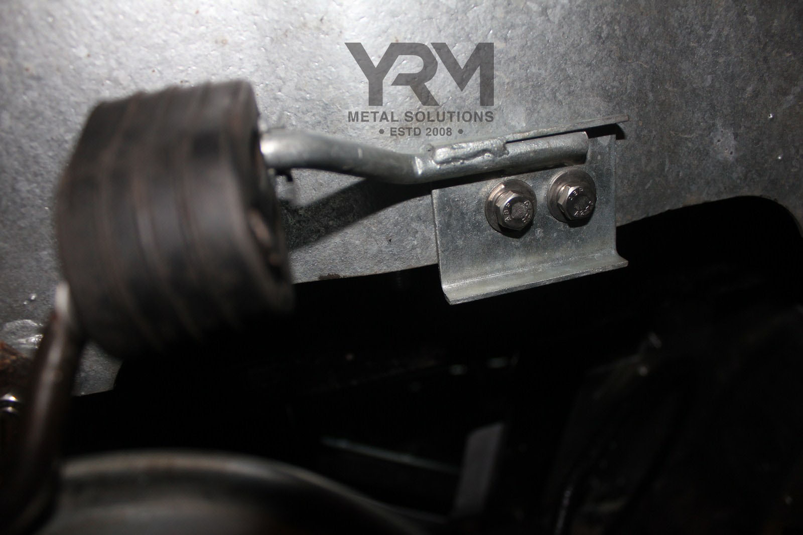
Which looks like a dead ringer for what I've got:

Again, I'll eyeball that more closely today, but it looks promising....
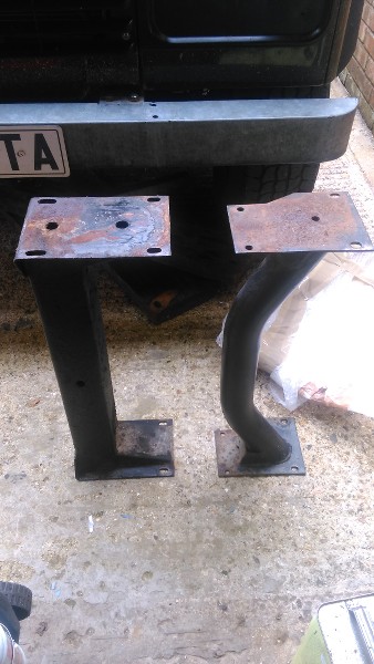
My problem then is the front hanger which doesn't seem to have any logical place to attach:

Anybody have a fix for that? Find a way to attach to the cross-member upper left in the pic?

A dangly bit and a U bolt around the pipe? Could be made to work....
-
Insists on putting a duplicate copy of one of the pics at the end there and can't get rid of it. Never mind...
-
Occurred to me that it would be a good idea to get the silencer sorted before the fuel tank goes back in - more headroom to see how to fit it and move around in. Back on this later...
See you over in the exhaust system department
-
Well, it's been a year or two since a 110 got an airing on this thread, so this is a bit of a this is what I've been doing and a few questions for those who know. Mine is a 1987 2.5NA diesel ex-army job, with a 1997 3.9 Disco engine. This was an insurance write-off vehicle, so having reduced that to parts I have lots of bits to play with. And trip over.
I've just had the main TD5 110 silencer boxes arrive from Island 4x4:
1 x Centre Silencer 110 TD5 (Britpart) WCE000040 (WCE000040) = £72.50
1 x Rear Silencer 110/130 TD5 (Britpart) WCG103020 LR066422 (LR066422) = £54.99Yeah, I know, but I wanted to make sure I understand what I'm doing before spending serious money, and they ought to last a couple of years.
So here we go.
The need for the different cross member has been covered above, with the nice comparative pic:
On 12/9/2016 at 6:55 PM, Quagmire said:Here's the one off my Disco with the bits welded on and the whole assembly set in place:

The cross-member is not central in its end-plates, I've set it in rearwards to get it as far away from the downpipes as possible. I'll drill the holes later, when I'm satisfied everything fits properly.
Seemed a good idea to fit the Disco heat shield before the manifolds go on, it attaches with the engine mounts:

I forgot and had to take the weight of the engine jacked up on the axle to get the thing on - best done before the engine goes in...
Standard Disco exhaust manifolds:

And the Disco downpipes:

Strapped the rear end to the cross-member so that I could get the front ends attached like so:

The cable tie just to keep the gasket in place while manoeuvering the down-pipes into place. Then with a jack under the back end, I set the gap fore and aft, and each side to 3mm...

Now the back end is in the right place (ish) relative to the engine
Bring on the Britparts....

The bolts welded to the front end plate of the middle section weren't long enough, so they had to go.
Then:

With a lot of scrabbling about and cussing, got the front end attached. Jack in place to support the downpipes, and to adjust the alignment at the manifold end of things as described above.
Centre box strapped up into approximate position and rear pipe bolted up:

No olive or rear gasket at this point.
This brings the rear of the thing out in what looks like the right position:

So far so good, but time to understand the hangars. I'll sort out some pics of my truck hanger points and come back on those along with my questions tomorrow

-
On 4/25/2023 at 6:39 PM, Phill S said:
And reading that and measuring it at 12mm stopped thinking. It's 24 tpi so I've no idea what it is, it's not on my chart metric or Imperial...
Double whammy - I'm there at last. I had no idea there was an M12 thread with a 1mm pitch - hence the 24 tpi measurement. Living and still learning...
-
 1
1
-
-
My question for today, is there a sender for the side/90 tank that has a low level warning light? I bought PRC8708 but no warning connection. I can see how to retro-fit one, but would prefer to get the right article.
First, an apology...
9 hours ago, Phill S said:all the fittings are M12 except the sedimentors, which are 1/2" UNF
No they're not! Double checked this today because I was puzzling over what fitted where. I'd looked up the blanking plug here:
https://www.lrworkshop.com/parts/NTC1612
And reading that and measuring it at 12mm stopped thinking. It's 24 tpi so I've no idea what it is, it's not on my chart metric or Imperial...
Anybody?
9 hours ago, Paul C said:I have been able to get the olives and female nuts, just need more m12 male tube nuts
Don't know what you have over there but guessing you're looking for this sort of thing?
https://www.island-4x4.co.uk/advanced_search_result.php?keywords=nrc9770&x=36&y=11
21 hours ago, Bowie69 said:anti surge feature/tank thing, if you peer down the fuel sender hole then you may be able to see it
Ere tiz:

Anti-slosh baffles all around the central box, which I assume is there to stop the gauge dancing about at low fuel level and to allow you suck the last little bit out of the tank
5 hours ago, FridgeFreezer said:are you just using the diesel pickup and into an LP pump then into a HP pump?
Yup. I'm pretty much sold on doing it this way now. At least, until I hear how much noise that little lot makes. The very tip of the fuel return pipe NTC2156 sits about 3/4" above the bottom of the tank, so that should function perfectly well as my pump feed. This little lot turned up in the post in time for todays efforts.

The back row will be the fuel supply to the engine. carp catcher, filter, FuelFlow LP pump and the HP pump. I'm going to pump the fuel from the side tank to the main tank as needed using the front row with some clever Dickery to manage the process. At least that's the plan as of now.
6 hours ago, markyboy said:Yes please
I bought 2 of these 52mm jobs to be able to monitor the transfer process as well as wanting a reasonably contemporary looking gauge for the main tank with a more useful display area...

My buddy is doing a lot of wood machining just now and driving me nuts with the sawdust. Anyway, about £12 each from AliExpress as I recall. Double that for taxes and carriage and wait 3 weeks and there you go. It's actually tolerably well made and seems to work well in bench testing. Gets a bit jittery at very low fuel level, but so do I. It talks to your phone over wifi, I connected to it without any problems. You get a table of numbers where you type in the sender resistance for empty, 1/4 - - - up to full. Empty and full easy to measure and I've guestimated the intermediate points. Once I have a running engine I'll fill the main tank 20 litres at a time and do a precise setup. Similary with Mr Wonky up front. We'll see how it works out in practice.
So, if you search or wifi fuel gauge on AliExpress and you'll find them all over the place.
This is who I bought from:
Holler if any problem.
-
1
-
-
Thanks both - I didn't explain myself very well! Converting from diesel to petrol I've got used to the idea that I'm going to be pulling fuel out through top centre of the tank and then pushing in the return somewhere else. Hence the question about the blanked off pipe on the RHS of the tank.
First thought was to use the PRC8318 in-tank pump discussed earlier in this thread, but I'm concerned about their reliability - I want fit and forget (as far as is possible!) and am going for a Bosch XJ6 type in-line. Yeah - I've heard they're noisy, but I have a cunning plan. And a New Zealand FuelFlow LP pump to supply that. I've had one of those running in another vehicle for the last 9 years which has performed flawlessly.
My other concern is the state of my tanks. Steel jobs both, and should have a good few years in them yet, but hard to tell what's been going inside. Cunning plan 2 is to be able to monitor those.
8 hours ago, Paul C said:I fitted an additional fuel gauge so I can see the level of both tanks at any time.
Yup - I've bought a pair of cheapo programmable jobs with a 270⁰ sweep. I'll post some notes on those if anybody's interested.
8 hours ago, Paul C said:been having trouble finding the correct pipes and fittings
You're probly there already, but on my '87 110 all the fittings are M12 except the sedimentors, which are 1/2" UNF.
My original plastic pipes are in very good condition and I'm pretty sure they are E10 proof, so planning to re-use those on the LP parts of the circuit. I'll stick an offcut in a jam jar of E10 and monitor that...
-
On 7/17/2022 at 10:03 AM, Phill S said:
I'll do some more homework and get back...
I'm back.
Just before I start plumbing up the fuel system, can anybody tell me what the pipe sticking out with the blanking plug is/was for? Item 25 below

Any reason not to use it for the return line? Planning to use sender STC1482 that doesn't have the built in pipe so I can reduce the line length and generally tidy up the pipework.

Thanks - Phill
-
Looks like a dead ringer to me...

Thanks again
Phill
-
1
-
-
Now that would make sense - thanks, I'll eyeball them up down at my workshop today. Odd that it's not listed though, workshop manual specifically says to replace it...
-
This item doesn't appear to be identified in the parts listings:

It makes the seal between the regulator, item 8, and the fuel rail. My regulator is going to be ERR6185 if that makes any difference. Anybody able to shed any light on that?
Thanks - Phill
-
And that means lifters too. Good ones are hard to find...
-
A different vehicle - an old Rover P5, but on a previous problem like this I took the drive belt off and turned the pump by hand. A bit laborious but worked and no risk of damaging anything...
-
5 hours ago, Stellaghost said:
I have 2 of them one at 112000 and the other at 182000 if they are closer to mileage your wanting to show I could post the one you want to you regards Stephen
Sadly not - my 110 has only done 5k miles. Or was it Km? Not many anyway. But thanks for the offer. If I have to go with fitting the Disco one I have that reads 61k, that would probably be my best compromise
5 hours ago, Nonimouse said:I fitted an RRC hard dash guage set to my first Hybrid, in exactly this place. It worked well. I think this will look really good - it's a nice set up
Interesting. A Hybrid is a 110/Defender or similar on a RRC chassis? Pardon my ignorance...
-
Just to try to shed a little more light on what I (think I) want to do. Still working out the practicalities, so every possibility it might fall in a heap and I revert to the original 110 config. Probably more detail follows than anybody wants, but stop reading if you get bored/have short attention span.
The story starts with a pre-Putin war plan to replace my 1987 stinky 2.5 NA diesel engine with a 3.9 V8. So I bought an insurance write off 1997 Disco 1. As a part of my refit I want to replace the 24v wiring with 12v. So I carefully removed the Disco wiring loom along with a mass of other useful bits. Here's me offering up the wiring in the dash area:

Yeah - that looks like it'll work. Still working out the cable runs, so plenty of opportunity for the plan to get scuppered. But I bet somebody's done it before...
Now the original Disco instrument cluster will sit nicely in the centre section, pic just to confirm the unit I'm working with for anybody that knows about such things:

And here's the guts of the speedo unit:

It is possible to push the white wheel around (1/10th of a mile spool) and have the miles increase, although there's a rubbery feeling of resistance which would most likely result in wear of the mechanism if I pushed it around for any amount of time.
Having got to that point I thought it worthwhile asking here if there's an easy way to push the higher register spools around, but I'm guessing it may be designed to be tamper-proof...
-
1
-
-
Thanks guys. Don't think the drill approach is going to work. Simple sum, if I set it up on the bench at 100mph, it'll take 10 hours to increase by 1,000 miles, 100 hours to do 10,000 etc. I should come clean at this point and say that I'm looking at putting the Disco 1 instrument cluster into my 1987 110. Ex-army truck, only done 5,000 ish miles, the Disco speedo I have has done 61k ish miles. You see the magnitude of the task.
I've rebuild the Disco transfer box and it certainly has the transducer drive to the speedo by electrical wiring. With the speedo out of the cluster you can see all the gears and sprags that operate the odometer and I'd been thinking there's maybe a simple way to flip the individual registers over. I'll put up some pics this evening...
-
1
-
-
The one that's going in. Would need to knock a fair few miles off of it to match up....
-
Changing the speedometer in my truck with a used unit and wondering if there's a way to change the odometer to match what's coming out? It's a stock 1997 unit
Any help/ideas gratefully received!
-
Recently did my 3.9, which was from a 97 Disco 1.
I just replaced with a bog standard cam, gears and chain. Here's the pics from my build up, which was just a matter of putting back all the bits that came off - and went like this....
Camshaft in and retaining plate on. Checking end float - I got 0.085mm:

Gears, chain and Woodruff key:

Spacer thingy:

Distributor drive gear:

Washer and bolt:

Don't know if that little lot sheds any light...
-
Great, I'll do some before and after measurements. If I can remember....
-
20 hours ago, Retroanaconda said:
I think you’ve identified the correct shafts
Cool - I'll go with that :-}
41 minutes ago, FridgeFreezer said:your front axle looks very tilted forward
Yeah - I've been thinking that myself, but I can't see any way it can be fitted differently. Not jacked up and nothing horribly bent. I've put the Disco 1 front springs on in place of the originals - can't see that would be a problem? 😕
-
I know prop shafts are a recurrent topic, and I have searched - honest. So I think I know what I'm doing, just looking for a warm fuzzy feeling.
So my 1987 110 has a Salisbury back axle and now has its 3.9 V8, R380 and LT230 (possibly) sitting in the "correct" positions. So attention turns to what prop shafts.
I think the rear one is easy, and it's the FRC8389:

A quick search at https://www.lrworkshop.com/parts/FRC8389 offers the cheerful comments:
by fandrich. 12th Oct 2020 16:50
Otokar Turkey produced the 300tdi Defender XD 110 with the 'salisbury' axle, unlike the UK 'Wolf' using the strutted 'P38'-Wolf axles and the 'P38'-Wolf 130"s 16S axles.
In the combination R380+'salisbury', the civilian 110"s use the FTC3905 prop.
However, the Otokar Defender XD 110" with R380+'salisbury' received this FRC8389 prop.
This makes FRC8389 / FTC3905 interchangeable and it can be assumed that FRC8389 is a HD variantThank you fandrich! The page is also currently showing that I can buy a Hardy Spicer unit for less than Britpart/Bearmach. Am I missing something or is that a no brainer?
Just to complicate things though, I measure the mid-point flange to flange length on my truck as 1,115mm, whereas on the above page we have:
by fandrich. 27th Nov 2019 00:50
1075mm compressed lengthThe angles at the flanges look ok, but 40mm extension seems more than I would have expected? Maybe just get one and offer it up...
I believe the correct front prop shaft would be FRC8386:

And whaddayaknow, the Disco parts manual gives the same number for the without catalytic part, but FRC8641 for the with cat. Which is what I've got from my engine donor vehicle. As far as I can figure out, it's about not fouling the cats rather than length though?
A return trip to https://www.lrworkshop.com/parts/TVB100610 shows FRC8386 has been superseded by TVB100610, which has notes:
Notes
300Tdi and Td5, not V8
Uses larger 93mm UJs, STC4807
Length: 604mmalso V8 accoding to microcat from 1A612405 / 2001I got excited yesterday because I started fitting the front prop shaft from my Disco 1 engine donor vehicle, and forgot to measure the flange to flange length. Duuh. Away from home for a time now, so I'll check that when I get back.
My main finding, and source of anxiety, is the angle that the prop shaft takes up. Fine down at the axle end:

I think...
But kind of worrying at the tf box end:

That looks awful. And not because I haven't cleaned it. Using the nice square edge of the flange as datum i get this on the shaft:

Seems like a bigger angle than I'd like?
That's also about 30mm of its extension from fully compressed that you can see there. Seems like a long way?
A bit of a brain dump, but any thoughts welcome. I'll be able to get on line periodically although I won't be able to get back to the vehicle for a couple of weeks...
-
13 hours ago, Mo Murphy said:
Wow, your chassis is very ... erm ... yellow ! 😯🙂
Why thank ee kind sir! My efforts to be able to see anything when I'm under the truck. Seems to work pretty well actually.
I think my final update on this (for the time being!) is the angle that the engine sits at:

With aid of my every expense spared gauge and the straightest bit of wood I could find I get 2.7º to the horizontal, using the bulkhead as my vertical datum. Seems about right as a general consensus.
The rear Disco 1 TF box bracket sets the vertical position at the back, which seems to be correct, giving me about ½" clearance between the top of the gearchange remote and the front edge of the seat box. I think I've got it about right....
At last!
-
2
-
-
59 minutes ago, Bowie69 said:
Better to look for an RRC rear prop
Looks like I need FRC8389? I have the Salisbury back axle.
https://www.lrworkshop.com/parts/FRC8389
https://www.johncraddockltd.co.uk/frc8389-propshaft-110-v8-rear-from-vin-252258-and-early-lse.html


V8 Exhaust
in Defender Forum (1983 - 2016)
Posted
Nice job!