


PaulMc
-
Posts
937 -
Joined
-
Last visited
-
Days Won
4
Content Type
Profiles
Forums
Events
Gallery
Blogs
Posts posted by PaulMc
-
-
On 11/7/2019 at 6:49 AM, Maverik said:
Do you know what crimping tool you need for them too?
I posted some info on the crimping tools that I use, here -
https://forums.lr4x4.com/topic/14892-wibbly-wobbly-speedo/?do=findComment&comment=802149
(the pictures have been ruined by PhotoBucket 😠 )
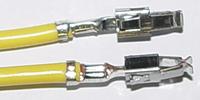
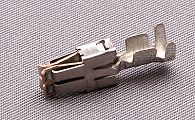
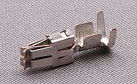
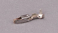
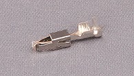
I now have two models of reasonably priced (Chinese
 ) ratchet crimpers in stock, which perform an adequate crimp on these Sumitomo 090 terminals, as well as the TE(AMP) 070 terminals used on the switch connectors -
For 0.25 - 1.0mm²

For 0.5 - 1.5mm²

-
4 hours ago, daveturnbull said:

PaulMc, yesterday.
Thanks Dave 😂
-
1 hour ago, cackshifter said:
B****dy mobile phones. And doing it on a train didn't help. Sorry. Stafford Vehicle Components sell them, try this one Link
That one's the Lucas-Rists 5-way wiper motor connector.
-
8 hours ago, David Sparkes said:
This shows it in situ, although the picture doesn't make it clear which is the main loom, I assume the description 'female part' means it's the white connector in the foreground, not the 'yellowed' connector that is mainly hidden.
The lighter connector in the forground is the male connector, with pin terminals.
The darker connector is the female connector (YPC10038), with receptacle terminals.
The female connector is on the vehicle's main harness, the male connector is on the tails from the column switch.
-
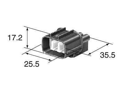
Sumitomo HM090 6-way
I can supply both the male and female connectors with terminals.
PM me.
-
 1
1
-
-
Yes.
There's a replaceable clear bulb and holder (STC1205) on the underside of the switch body.

http://www.rimmerbros.co.uk/Item--i-STC1205
-
There are several connector manufacturer's products used on the D2's harnesses.
PM me on here, with what you're looking for.
I've much more than I have listed on eBay.
Paul.
-
 1
1
-
-
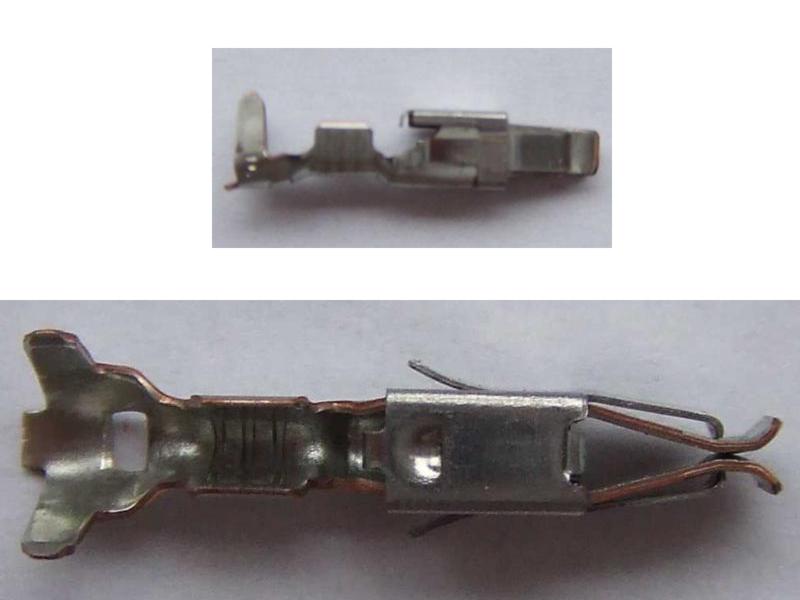
1 hour ago, Green200tdi said:
So plug goes together and clips in tight wires nice n tight heater comes on but can’t get this to go in grey plug
guess terminal round wrong way?

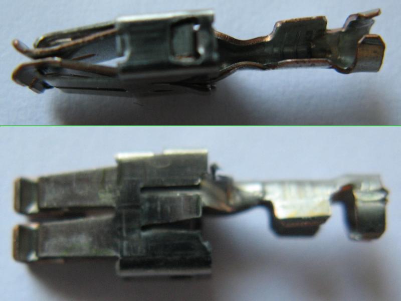
The secondary terminal lock will only go in one way.
Your picture shows the side that goes into the connector towards the terminals.
You have it the correct way up - the 3 x pegs go in above the terminals, stopping the terminal retainers from lifting.
This image shows the connector's correct top/bottom orientation -
Before inserting the secondary terminal lock, make sure that the terminals are correctly seated in their cavities.
-
I am.
I have the 3-way connectors to fit the TD5 blower.
I'll PM you tomorrow.
-
1
-
-
On 7/30/2019 at 10:23 AM, Gluv said:
I have the wolf parts manual so have all the proper numbers but searching on the net has turned up nothing. I was told at craddocks that military parts are now only available to military customers. I don't know how true that is .
Gluv
There's not a 'kit' as such, parts have to be sourced individually.
In the case of the grommet 531689 (and some of the screws and washers), you have to buy a bag of 10
AFAIK, all of these parts are available from a main dealer or Genuine Parts reseller, to anyone who orders them.
Military parts have always been available from dealers (if you know the Civvy part number) - although, this may have changed.
I'll check this out the next time I'm at my local dealer's parts counter.
From previous experience, I would take anything John Craddock says, with a LARGE pinch of salt.
.
-
From the 'Wolf' ISPL -
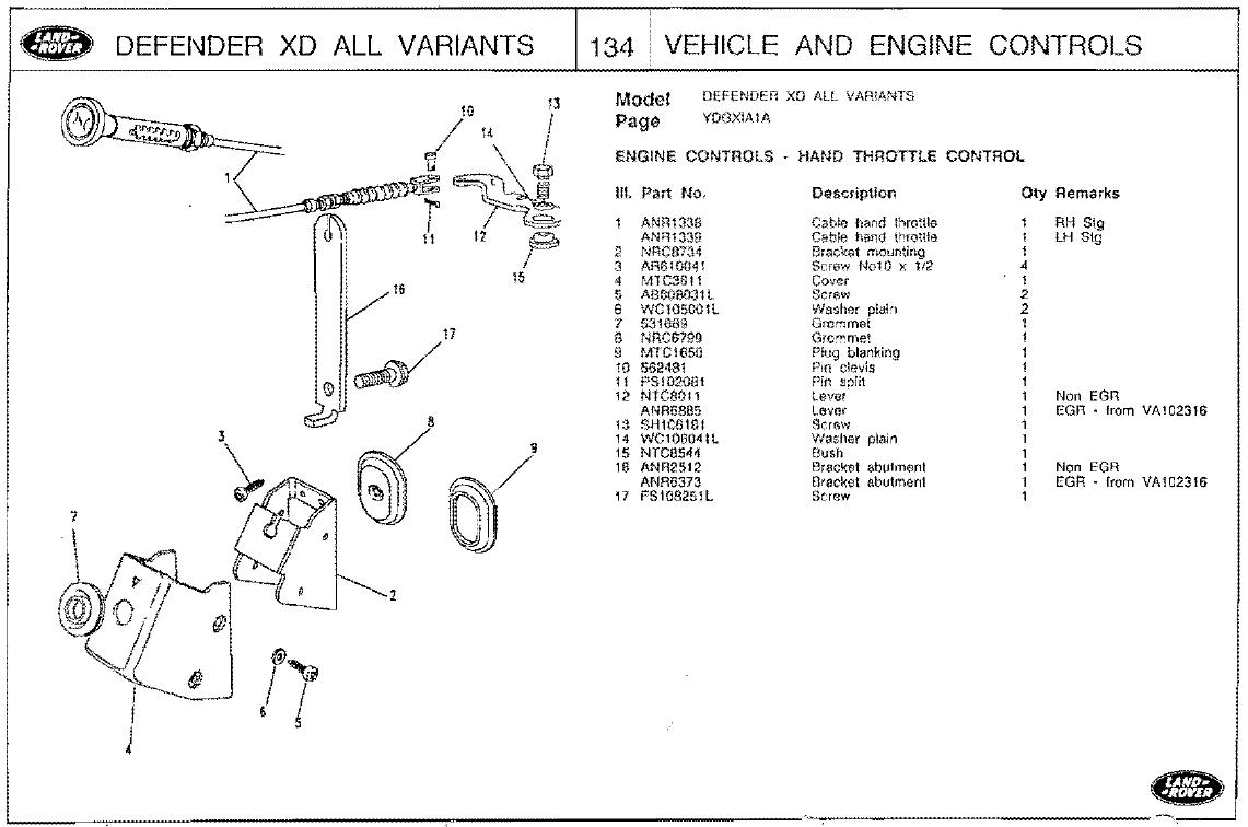
.
-
-
3
-
-
13 minutes ago, Anderzander said:
Is Paul still around Mo? Not seen him post for ages.
 Still lurking...
.
-
It's for the headlamp levelling switch.
-
18 hours ago, JonathanR83 said:
Can you please let me know what's the reference on Polevolt for
Cavities Terminal
2, 5, 8 000 979 135 (1,0 mm²)

If you have a Link on Polevolt..
By the same Time i am looking for the reference of the terminal on this Relay crimp
Reference : 8E0 937 527

VAG terminals to fit the relay socket 8E0 937 527 are -
Smaller terminal
To fit two cable sizes, both available as -
A Repair Wire - 000 979 133 (1.0 mm²)
A Crimp Terminal - N 906 844 05 (1.0 mm²)
A Repair Wire - 000 979 225 (2.5 mm²)
A Crimp Terminal - N 906 845 05 (2.5 mm²)
Larger Terminal
To fit one cable size, available as -
A Repair Wire - 000 979 236 (2.5 mm²)

A Crimp Terminal - N 103 197 01 (2.5 mm²)
I can't find a match for 000 979 236 (N 103 197 01) from anyone other than VAG
Polevolt sell relay terminals for the MTA Modular Fuse and Relay System, these look very much like the 'Timer' type terminals used in the VW relay sockets.
6.3mm Terminals for relay modules 1 - 2.5mm cable, Ref: 3-2030
6.3mm Terminals for relay modules 2.5 - 4mm cable, Ref: 3-2050
These look very much like the Terminal used on the Repair Wire - 000 979 135
Which is also available as a Crimp Terminal - N 907 326 03
2.8mm Terminals for relay modules 0.5 - 1mm cable, Ref: 3-5620
2.8mm Terminals for relay modules 1.5 - 2.5mm cable, Ref: 3-5630
These look very much like the Terminal used in the relay socket 8E0 937 527 above.
Unfortunately, Polevolt don't ship outside of the UK.
Vehicle Wiring Products will ship abroad - http://www.vehicle-wiring-products.eu/


.
-
C0195 is a 3-way female Econoseal III 070 connector -

It's wired as follows -
Terminal 1 - White/Green - Ignition-switched live, from fuse 12 (10A) in the bulkhead fuse box
Terminal 2 - Black - Earth, to header C0550 (earth stud on bulkhead in engine compartment)
Terminal 3 - Black/Red - Signal, to speedo Pink ISO connector (C1060)
The wiring for these is already in your main harness (from connector C0448), and would normally go through connector C0162 on the engine harness, that mates with C0448 on the main harness.
In C0448 (and C0162) the wires are on the following terminals -
White/Green - Terminal 12
Black - Terminal 6
Black/Red - Terminal 10
I can supply the Sumitomo 14-way male connector (C0162), if you wanted to make your own engine harness?
.
-
The speedo transducer connector (C0195) is on the engine harness.
It's wired via the main harness to engine harness connectors C0448/C0162
.
-
The four connectors in your picture, are -

A. Main Lighting Switch (LH side of column)
B. Rear Fog Lamp 'one-touch' ECU (behind instrument pack)
C. Wash/Wipe Switch (RH side of column)
D. Horn/Dip/Flash Switch (LH side of column)
For the rear fog lamp switch -
1999 - 2001 - have the Lucas type rocker switch down by your right knee
2002 - 2006 - have the push/push type in the console in the centre of the dash
.
-
The 14-way Grey connectors are Sumitomo HW series - I have these complete.
They are available from Land Rover, in a bag of 10 housings, without the White plastic terminal lock, without terminals, wire seals or cavity blanks.
The 4-way connector is a TE 2.5mm pin and socket, made for BMW.
These are not available from Land Rover, but can be bought at a BMW dealer.
I've previously posted-up some BMW part numbers for these, I'll have a search and see if I can find my post.
.
-
1
-
1
-
-
Mo,
I don't know what the washer pumps draw, but both the front and rear washer pumps are wired in 1.0mm² cable, which is good for 16A
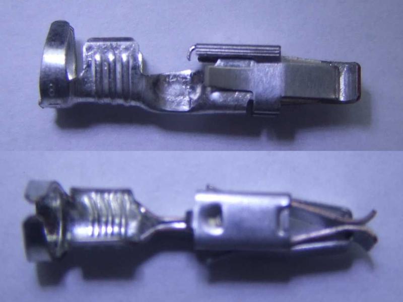
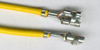
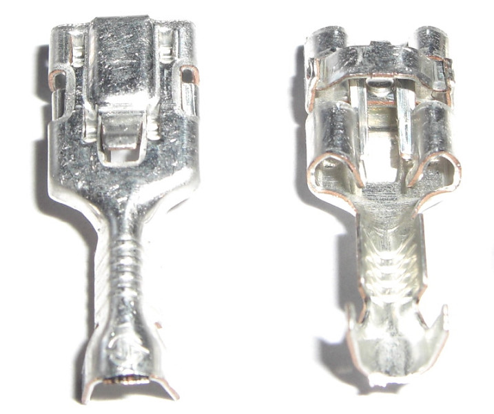
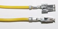
I'm a bit dearer than Autosparks, but I have the proper connectors, with 'PosiLock' terminals, which have a sprung platform which locks them to the male tab.
Available in 'Natural' or Black, they are supplied with 2 x terminals, for £0.95 each + £1.25 for 1st class P&P (cheaper than Autosparks)


.
-
1
-
1
-
-
On 8/18/2018 at 10:12 AM, groundzero4wd said:
Hi paul,
the blue one is 0287 the red one i don't know. it's for a customer that drives around without dashboard in his td5.
he want's one black one and 2 red ones. how do i order and how do i pay? postage will be to Sweden
Sorry for the delay in getting back to you, I thought that I'd found some stocks of the Blue headers - but, after chasing them for an answer, all they had was the Blue terminal blocks, without the splice cap 😞
Anyway, I'll send you a PM regarding the headers you want.
Paul.
-
The switch you have (YUG000540LNF) is designed to switch the earth side of a relay's coil (terminal 85) to earth.
It should be wired from relay terminal 85 to switch pin 1
The switch switches pin 1 to pin 4 in the 'on' position.
Pin 4 should be wired to earth.
As in this diagram -

The switch terminals should be wired as follows -
- Pin 1 - From the earth side of the Relay (Pin 85)
- Pin 2 - To Dash Illumination Header (or an adjacent switch)
- Pin 3 - Not Used (but connected internally to Pin 4)
- Pin 4 - To Dash Earth Header (or an adjacent switch)
- Pin 5 - Live from Accessory side of Relay (Pin 87), for 'tell-tale' orange LED
Although you have the switch wired incorrectly, the reason that your background illumination is working, is that it's finding an earth path through the bulb of your work lamp.
You'll not get the tell-tale LED working with it wired this way.
If you don't need a relay with your work lamp, there are a few ways that you can wire it to this switch -
1. Run the live directly to the lamp, with its earth run back to the switch - however, this way has it's own problems -
As there's no output side of a relay, running a wire from the live side of the lamp to switch pin 5, would light the tell-tale LED permanently ☹️
Some lamps may be earthed through their mountings.
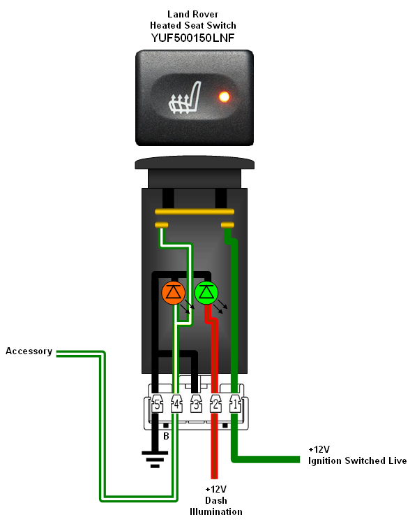
2. Change the switch body of YUG000540LNF for the body from a live-switching switch.
The cheapest option for this, is the Defender TDCi heated seat switch YUF500150LNF, which costs just under £10
http://www.rimmerbros.co.uk/Item--i-YUF500150LNF
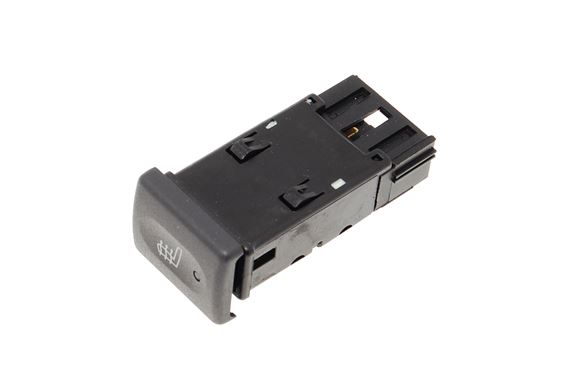
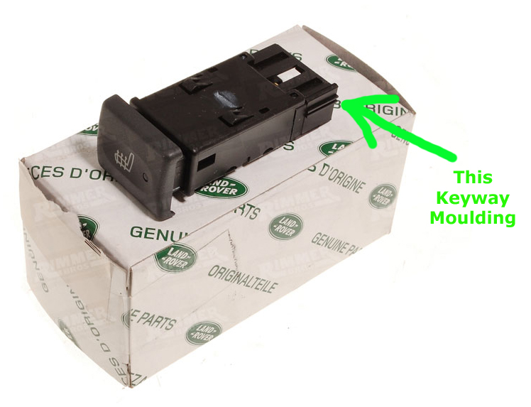
Apart from swapping-over the switch fronts, the only other modification is to remove the switch's body keyway -
YUF500150LNF also uses the Black 5-way connector, and should be wired as follows -
- Pin 1 - Live in (from fused supply)
- Pin 2 - Dash illumination
- Pin 3 - Not used (but is internally connected to Pin 5 - Earth)
- Pin 4 - Switched live out to accessory (or relay)
- Pin 5 - Earth
3. Modify YUG000540LNF internally, to turn it into a live-switching switch - this is easy and costs nothing 😀
Open up the switch, and cut the Brass track, as shown in Red, here -
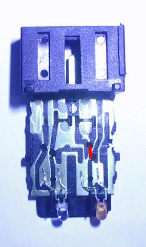
This separates pins 3 and 4, meaning that the pinouts would then be -
- Pin 1 - Live in (from fused supply)
- Pin 2 - Dash illumination
- Pin 3 - Earth
- Pin 4 - Switched live out to accessory (or relay)
- Pin 5 - Live for tell-tale LED
You could connect pins 4 and 5 internally so that the tell-tale LED lit in the 'on' position - but, it's just as easy to crimp a loop of cable from the terminal in pin 4, round to pin 5
.
-
On 8/26/2018 at 2:57 PM, Bigj66 said:
Fitted the console switch for the rear spotlight using a genuine auxiliary lamp switch to keep everything looking standard. It’s the one with the number 2 next to the symbol. The switch background illuminates when the side lights go on but the orange tell tale won’t illuminate when the work light is on. Wired up as per the thread in the tech section and would expect the tell tale to work when the switched side of the contact goes live so maybe the switch is faulty.
As this switch switches the relay's coil to earth, there's no internal positive connection to the tell-tale LED.
To illuminate the tell-tale LED, you need to run a wire from terminal 87 on the relay, to pin 5 on the switch.
-
1 hour ago, groundzero4wd said:
Hi PaulMc, are you still able to supply those header and terminals? i did visit your ebay page but couldn't find them there. i should need the bleu and red ones.
best regards, Björn
Hi Björn,
I haven't got the headers listed on eBay.
I've sold out of the Blue headers, and I'm still trying to source some more.
However, a Black header (which I have stocks of) can replace a Blue header, by including a loop of cable between the terminals in cavities 3 and 4, when you crimp on the new terminals.
Hopefully these diagrams, shown from the cable entry side, explain -
Blue header

Black header

I also have the Orange (Red) headers -


The headers are £9.95 each + P&P
I supply each of them with 20 x terminals for 0.5 - 1.5mm² cable.
If you have a Black one to replace a Blue one, I'll include some terminals for 2.0mm² cable.
What are the connector numbers (from the Electrical Library) for the headers you need to replace ?
Paul.


Td5 hazard warning light switch
in Defender Forum (1983 - 2016)
Posted
Sorry for the late reply.
The heated seat loom shouldn't affect the operation of the hazard switch.
Maverik has already answered correctly, regarding the hazard switch's illumination and operation.
It is probably just the bulb.
If you remove it from the switch, you can test it by putting 12v across the contacts on the bulb holder.