


SteveG
-
Posts
3,629 -
Joined
-
Last visited
-
Days Won
8
Content Type
Profiles
Forums
Events
Gallery
Blogs
Posts posted by SteveG
-
-
I’ve seen a number of custom bike and car places using wago connectors for junctions in wiring up. Any views on using them for automotive use?
https://eshop.wago.com/JPBC/0_5StartPage.jsp?zone=6

Both the 222 and 221 have automotive use listed as an application by Wago, rated to 32A and accept 0.2 to 4mm squared wire, so fine for most wiring applications like lighting, cdl etc. The only issue I can see is they have a max operating temp of 85 deg C. Personally, I don’t plan to use them outside the interior, and most thin wall cable is only rated to ~100 deg C anyway.
They seem to be a neat way to junction things like tail lights, indicators, cdl etc. where you can have up to 6 outputs off a single feed.
Thoughts?
-
Thanks Al and Wes, useful info.
cheers
Steve
-
Bit of an extreme way to keep warm...
-
3 minutes ago, FridgeFreezer said:
That's perfick, thanks Steve, pretty sure I'm going to get me one of those for the impending 109 rewire! Just need to get the crayons out & convince myself the scheme can work before bending the credit card.
Let me know if you need one bringing back, I should be out there again in March, April and May.
1 minute ago, skauldy said:Ahhh. I was going to ask would you mind putting me down for one of the bussmanns and then i seen the date you posted it.
I have been looking at the m unit also. Great price compared to other pdu's
Likewise, if you need one bringing back they are not bulky.
-
On 2/26/2018 at 6:55 PM, BogMonster said:
Seems quite bearable these last few days........................


So Stephen, how many months (or weeks
") ) of the year do you get weather like this?
) of the year do you get weather like this?
Very jealous btw.
-
Sure, this pic gives you the best idea...

As shown on the left hand pic, the bus bars are internal connecting to one pin of the fuse on both sides of the RFRM. These pins are not exposed on the underside, even though you can see 7 holes. The holes on the bottom row are left to right - 2nd pin of fuse; not used; 86 of relay; 87a; 87; not used; 2nd pin of fuse. I assume the not used ones are there for the non bus bar and custom versions of the RFRM.
You insert Delphi Metri-Pak 280 connectors into the holes...


On the topside, the far left and far right pin receptors are built in as they’re connected to the internal bus bar. The rest of the pin receptors, including the relay, are created from pushing in the metri-pak connectors.

Fortunately, my existing superseal crimp tool with the 2.8 opening was a perfect fit for the 280 connectors.
All good so far, apart from the built in pin receptors connected to the bus bar for the fuses were really tight, needing a set of pliers to insert fuses.
Hopefully this helps, let me know if you need to know anything else.
Cheers
Steve
-
I don’t think Motogadget call out needing to protect when switching inductive loads, however, it seems universal with these MOSFET based PDM’s, that the best approach is to fit a suppression diode across any inductive load.
The plan is to have the motogadget switch via an Albright isolator the ignition switched feed for the Bussmann RFRM’s (Relay and fuse power distribution unit) two 100A capacity busses. The thought was to use a TVS diode on the output to protect against any potential inductive kickback.
-
Thanks for the reply TSD, the motogadget has an over voltage protection between 16-40V on it’s supply input, but I don’t know if it has the same on the outputs. I’ll drop them an email and see what max clamp voltage it can cope with. Each output is essentially a MOSFET, so it’s designed to cope with a short circuit condition, and will shut down the output.
cheers
Steve
-
Started to snow here, looks like it will be testing my £90 gazebo to the limits over the next few days
 and it’s lasted so well so far

-
 2
2
-
-
So I’m planning to use a TVS diode to protect the motogadget when it switches the main ignition feeds and I have a few Q’s about specs. The littlefuse SLD series appears to be a good one to use.
For the reverse stand off voltage is 15V ok (just higher than normal level) or do I go a few volts higher to give room? I assume you don’t want to go too high to keep the clamp voltage down. It’s 24v for a 15V VR diode.
Also, for this type of application of protecting from switching loads, is it better to go bi-directional or un-directional for the diode? Both types are available.
Any help appreciated.
Cheers
Steve
-
I don’t think it is true, as when I looked a few months ago there were several people who had use easyweld on birmabright.
Can’t be arssed to search on google again, but here’s a link on LR4x4...
-
1 hour ago, cackshifter said:
It may well not be true, but I was told birmabright was a bit sporty when it gets hot as it contains magnesium. I never tried welding that (but I have glued it successfully with epoxy resin) .
-
You could get them tig welded, or if you have a map bottle torch, you can buy some Durafix Easyweld rods and braze them...
https://rover.ebay.com/rover/0/0/0?mpre=https%3A%2F%2Fwww.ebay.co.uk%2Fulk%2Fitm%2F291366831507
Search on YouTube for durafix easyweld and you’ll see some videos on how to do it. I’ve bought some for the panels on my range rover classic, but I haven’t got round to doing the panels yet.
cheers, Steve
-
Congrats on the purchase, looks like you’ve got a good buy there with all of the work done.
I’ve had three of the 2000/2001 spec 4.6 Vogue’s and I think they were the best for spec, interior and even reliability with the 4.6 liner issue being the only major downside. Apart from drowning the first one at 10 months old
 , the 2nd went past 100K before I sold it, and the 3rd past 210K miles.
I never had any major issues with the standard air suspension set up, if the bags and lines are kept in good condition you should be fine. I had a water pump pulley and front diff go on the 2nd one, both done by LR under warranty, and both probably caused by off-roading.
The 3rd one just needed the brake accumulator changing (soft pedal on start up), drivers door handle replacing and the hevac screen/control unit swapped. I’ve never had an issue with o-rings or blend motors, but I’ve always run hevac on auto with air con all year round on all my vehicles.
Come the warmer weather, I’d be tempted to fully flush the engine and heater matrix, replacing the water pump, any worn pipes, thermostat and the radiator. You get a lot crystalline build up over time, especially if the previous owners haven’t been religious about use of OAT and frequency of changes. It will be a worthwhile investment knowing you’ve got a fully working cooling system on the 4.6.
Have fun with the new purchase.
cheers, Steve
-
Just to fit more line on, especially as most of comp guys now use 11/12mm synthetic, so you don’t get much on a standard drum.
-
Most cars don’t fuse the starter motor feed. What are people’s thoughts on this? Good practice to fuse it of not?
A number of vehicles have a core feed wire from + terminal on the bat to starter, and then a core feed + wire to main fuse block. Some have main fuse block fed from bat directly. Again any pros & cons against this, or is it just a way to keep cable costs down?
VSR load rating. The max current draw of the range rover classic VSR is 40A, yet you can have it feeding front heated screen (2x 25A), rear screen 30A, and optionally split charge when fitted. Assuming that LR didn’t just ignore the max operating limit, is there something I’m missing here?
Similarly, the existing ignition relay doesn’t seem to be heavily rated. I’m planning to use a Bussmann RFRM as my main relay and fuse block. It has two 100A busses. If I used an Albright SPST isolator instead, I’m assuming I’ll be ok for this to be kept fully open all the time ignition is on, as it’s rated - Thermal Current Rating 100% 250A
https://www.firstfour.co.uk/albright-su280-isolator-250a.html
cheers, Steve
-
On 2/1/2018 at 4:59 PM, FridgeFreezer said:
TBH I'm being half tempted by the idea of just buying the "Useful tools" one to do it properly, as I could always flog it on ebay later if I get bored of flanging things
It's a bit extravagant but I've been saving pennies specifically for the purpose of sorting things like this with the 109 and doing it properly, and money spent on tools is never wasted.
I’ll probably need some custom hoses, as when I fit 4.6 in range rover classic I’m also using an aftermarket Hevac.
So if it helps, you could have some funds towards tool for borrowing when needed, or alternatively making up ss sections.
-
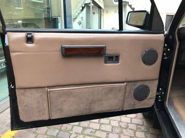
Personally, I would go with the leather option, or a good quality leatherette than might be harder wearing, and have it done by a local trimmer.
I was think of putting carpet on the lower panel, like the CSK version, just as it’s easily kicked on exiting and it would make it more resistant to scuffs/knocks.
For the lock mechanisms, you should be ok, as these are the same as Defender models and they cope ok with the various retrims in leather that the later 90’s & 110’s have had done.
-
Bussmann RFRM ordered along with relays, connectors and some other items from Waytek. Shipped same day last night, so depending on how quickly the parcel forwarding service turns it around, it may be here by the end of next week.
I went with Waytek, as they had all the items I needed, otherwise Ian’s finding of connector concepts look like a good option, and slightly cheaper too.
-
11 hours ago, KrisDR said:
Just what I needed ... a third option
")
That’s easy, unless you want it to look like it came from the factory, just go with the one you like the look of the most.
In case you didn’t know, you’ll also need two brackets for the fog/driving lights if you go for the later type, but they seem widely available, so you should have no problems in sourcing some.
cheers, Steve
-
Just as an FYI, my Spanish 89 2 door (2.4 VM Turbo D) came with this type of front spoiler...
https://www.famousfour.co.uk/new_parts/ff_part?part=24705
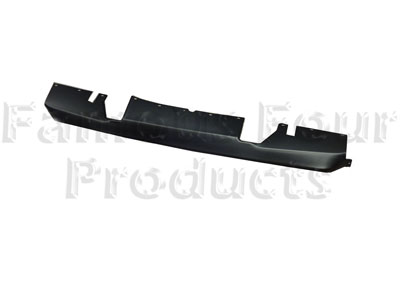

They break up and are often removed, so it’s probably the reason why yours didn’t have a spoiler.
cheers, Steve
-
8 hours ago, Red90 said:
I've used the Bussman before. They are nice. Love Waytek. The only problem is they have high minimums. They are designed for selling to businesses.
Thanks, that’s good to know. They seem to be good quality, and fairly compact for the amount of circuits you can run from them.
1 hour ago, Cynic-al said:I never had any problems with the stock connectors... maybe I was just lucky
How are you planning to run the engine?
MegaSquirt which is all new to me, so hopefully I’ll be relying on experience and expertise of others on here. Neil, V8Freak, has a Thor intake prepped for MS I can use, but everything else will need to be built up.
As I’m wiring everything from scratch the plan is to also run earths to busbars and then back to battery. I’m not sure if this is worth the effort or not. The SaeftyHub has a built in busbar, and a couple of additional ones should do. Thoughts anyone?
I’ll use LED’s as much as possible, so current draw on a lot of the circuits won’t be high, so I don’t need massive earths running everywhere. I’m toying with idea of using the a motogadget m-unit, which is earth switched for the trigger circuits and again on the bussmann I can earth switch the relays, so the majority of the switch circuits will be very low current.
For higher draw circuits like the heated screens, fans etc. I’ll run their own earth circuit rather than share. So I’ll only need to run bulky high current wires to the SafetyHub, Bussmann and Motogadget. Well that’s the initial plan.
-
1 hour ago, ianmayco68 said:
Personally I'd fit new deutsch connectors as you say modern ones are better at keeping moisture out , were did you get that fuse board from Steve ?
cheers Ian
Hi Ian, I got it directly from BlueSea on Amazon in US as it was much cheaper than here and I’m out there fairly often, you can source it in uk here...
http://www.rjsmarine.co.uk/7748-safetyhub-150-fuse-block although it’s still cheaper ordering on amazon and using their Int’l shipping.
57 minutes ago, FridgeFreezer said:I like the RFRM, how much are they & where do you get them?
Hi John
The best source appears to be here... https://www.waytekwire.com/item/46354/EATON-s-Bussmann-Series-15401-2-0-1-0A-RFRM/
I haven’t ordered yet as I plan to pick it up on one of my next trips over as they don’t ship internationally. I won’t have time on next week’s trip, so I may ship via a forwarding service. They are $82 plus cost of terminals, seals and plugs. The single bus, 5 relay version is about $30. If you want I’ll let you know when I’m ordering, and you can tell me know if you want me to order an additional one etc.
-
Input/advice needed on re-wire please...
For context, my 2 door is not one of the first fifty, or a rare/ unique RR. It’s a 1989 Turbo D registered in Spain, imported by me, and I’m in the process of rebuilding it from the ground up, doing a LHD to RHD conversion, and replacing the 2.4 VM, LT & BW combo for 4.6 V8, ZF & BW.For the RHD to LHD conversion I sourced a 1991 Vogue SE rust bucket of a donor car. The plan was to use the RHD wiring looms from the donor, however, it had been hacked about for an aftermarket alarm, had two ignition switches with Scotchlocks everywhere under the dash and rusty connectors throughout. The original LHD loom would need changing about a fair bit for RHD, and would need a number of additions for central locking, electric windows etc. etc. as well as moving relays around due to the lack of recessed footwell positions.
So I’ve decided to completely re-wire everything. I’ve ordered, just arrived, a Blue Sea SafetyHub 150 for the main power distribution + permanent live circuits, and plan to use a Bussmann RFRM with dual busses, 10 relays, and 40 fuses for the circuit power distribution. Heated front and rear screens will be fed via a VSR off a 100A feed from the SafetyHub 150.
For the new additional circuits, I plan to use Deutsch connectors (DT & DTP).
The existing RR light units use Lucas Rists circular connectors, 7 way on the rear, 3 way up front. I’ve checked and they are available new, however, as the donor’s rusty connections show, they are not as good as the mordern equivalents. So do I swap out the Rists for Deutsch, or go for new Rists and fit them in the new looms where required?
Any advice/comments always welcome.


cheers, Steve


 and it’s lasted so well so far


Wago connectors
in Modified Vehicle Builds & Special Projects
Posted
Thanks for the info.
They’re designed for stranded and single core.
i just tried the 222 series out with 1mm2, 2mm2, and 3mm2 and all fit ok and are very secure...


As you can see from the last pic, it clamps them evenly and securely.
You could go belt and braces and fit ferrules. I have some of these that I ordered to use in the motogadget terminal blocks...
The max that will fit with ferrules, is 1.5mm2, as you can see the 2mm2 only just fits.
Personally, from seeing how well it clamps all the wires tested, I wouldn’t worry about fitting ferrules.
I’ve ordered some 221 series blocks off Amazon today, to see how they are. They also have a fully flat back compared the 222 that have about 40% of the back angled, as you can see in pic 2. I plan to mount the connectors on the back of the fuse block etc. mounting bracket, so I suspect the 221 series will be better for this.
cheers
Steve